Quantcast
Channel: Electronics Projects – Dr. Scott M. Baker
Viewing all 118 articles
Browse latest View live

Z80 Retrocomputing 6 – RC2014 TIL311 Front Panel Board

$
0
0

I was so pleased with the Bus Monitor board that I decided to also build a “front panel” board.

[TODO - Insert video here]

This front panel board also uses TIL311 displays.

Design

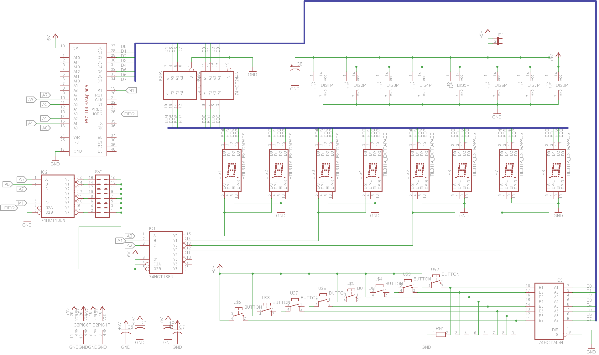
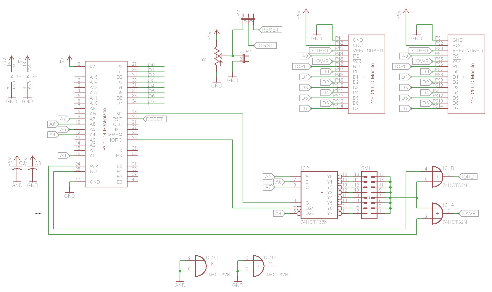
Here is the schematic:

RC2014 Front Panel w/ TIL311 led displays

If you haven’t read my other posts on the Z80 retrocomputer, please start with the first one, as it provides necessary background material.

I’ve already covered the TIL311 in a previous blog post, so I’ll talk about it briefly. It’s an older display, you can find them on ebay. The display uses a small matrix of LEDs and takes a 4-bit value as input. It’ll display a hex digit from 0-F. In addition to the digit, it can also display a left or right decimal point. It as a latch bit that can be used to tell it when to latch data.

Address decoding uses a pair of 74HCT138N 3-to-8 decoders. The first decoder (IC2) decodes A5, A6, A7. This allows putting the front panel board on the addresses 00, 20, 40, 60, 80, A0, C0, or E0. The second 74HCT138N decodes the A0 and A1 to select the digit. For example, if you select address E0 on the first 74HCT138N, then the digits will be at address E0, E1, E2, and E3. Since the displays are 4-bits each and the data bus is 8-bits, there are two digits per IO port.

There’s also a 74HCT245N bus transceiver that is used to implement an input port which will be the on the fifth address of the range (E4 in our example). This input port is connected to eight pushbuttons. Each pushbutton has an associated pull-down resistor (a 9-pin SIP resistor is used on the board).

Because the TIL311 displays are TTL devices and have a relatively high sink current, it’s important to buffer them. Otherwise our Z80s drive capability would be consumed by the TIL311 displays, leaving little remaining to drive the actual peripherals on the bus. That’s the purpose of IC8, a 74HCT244N buffer/line driver. This buffers the data bus, so the TIL311 displays do not load the bus.

Implementation

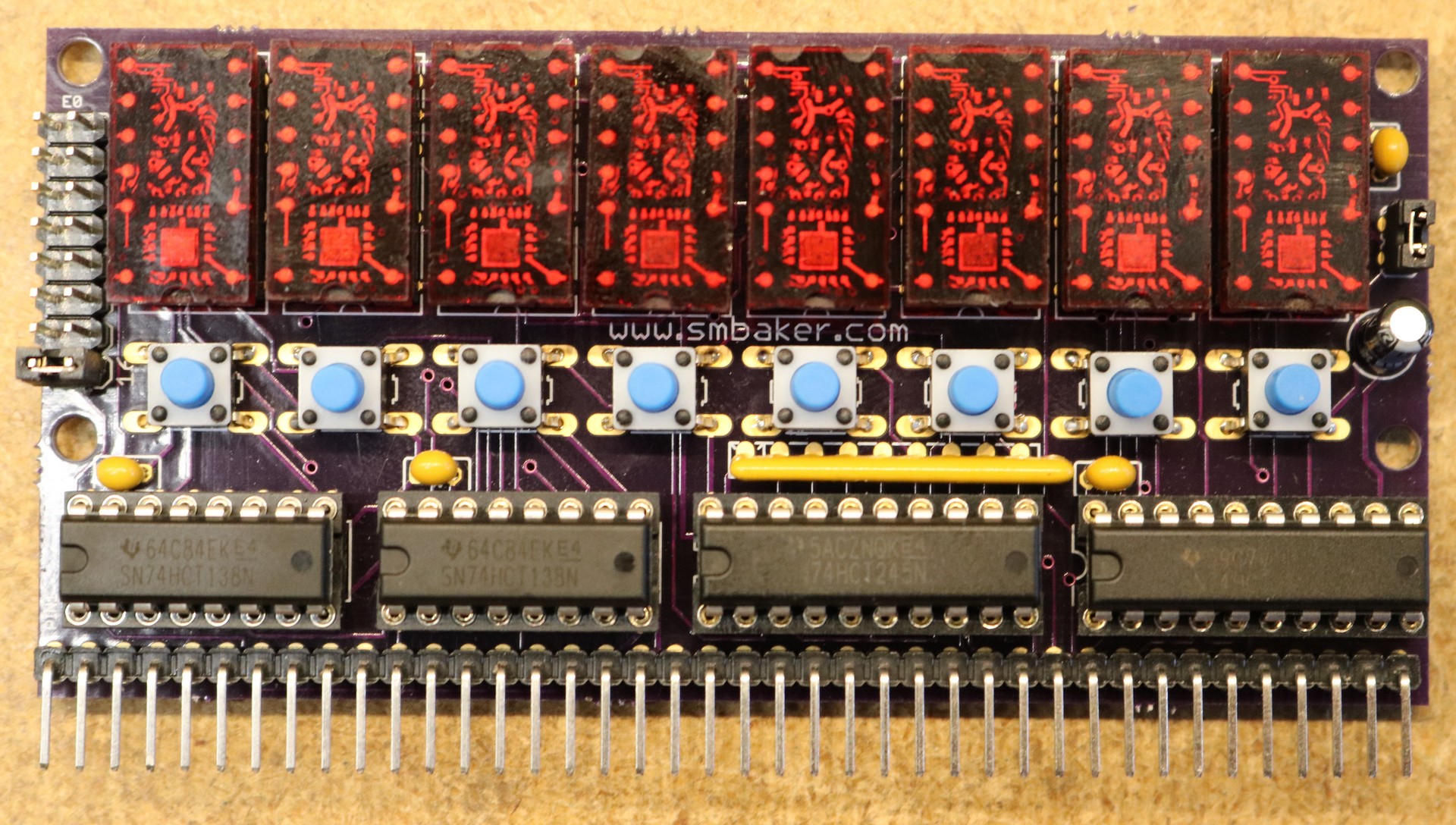
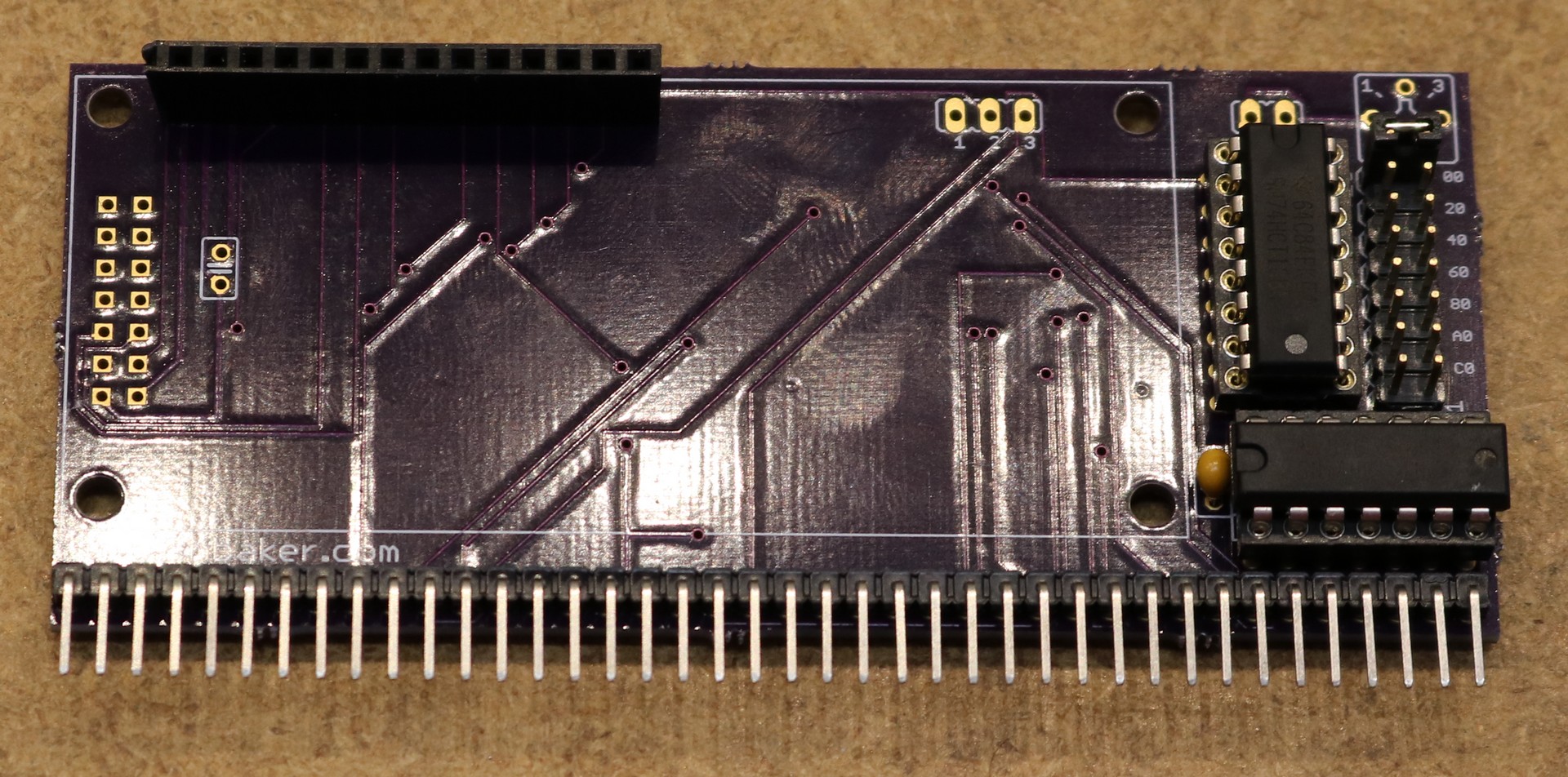
As usual, I had a board fabbed at Osh Park, so it’s in the usual Osh Park Purple:

RC2014 TIL311 Front Panel, Assembled

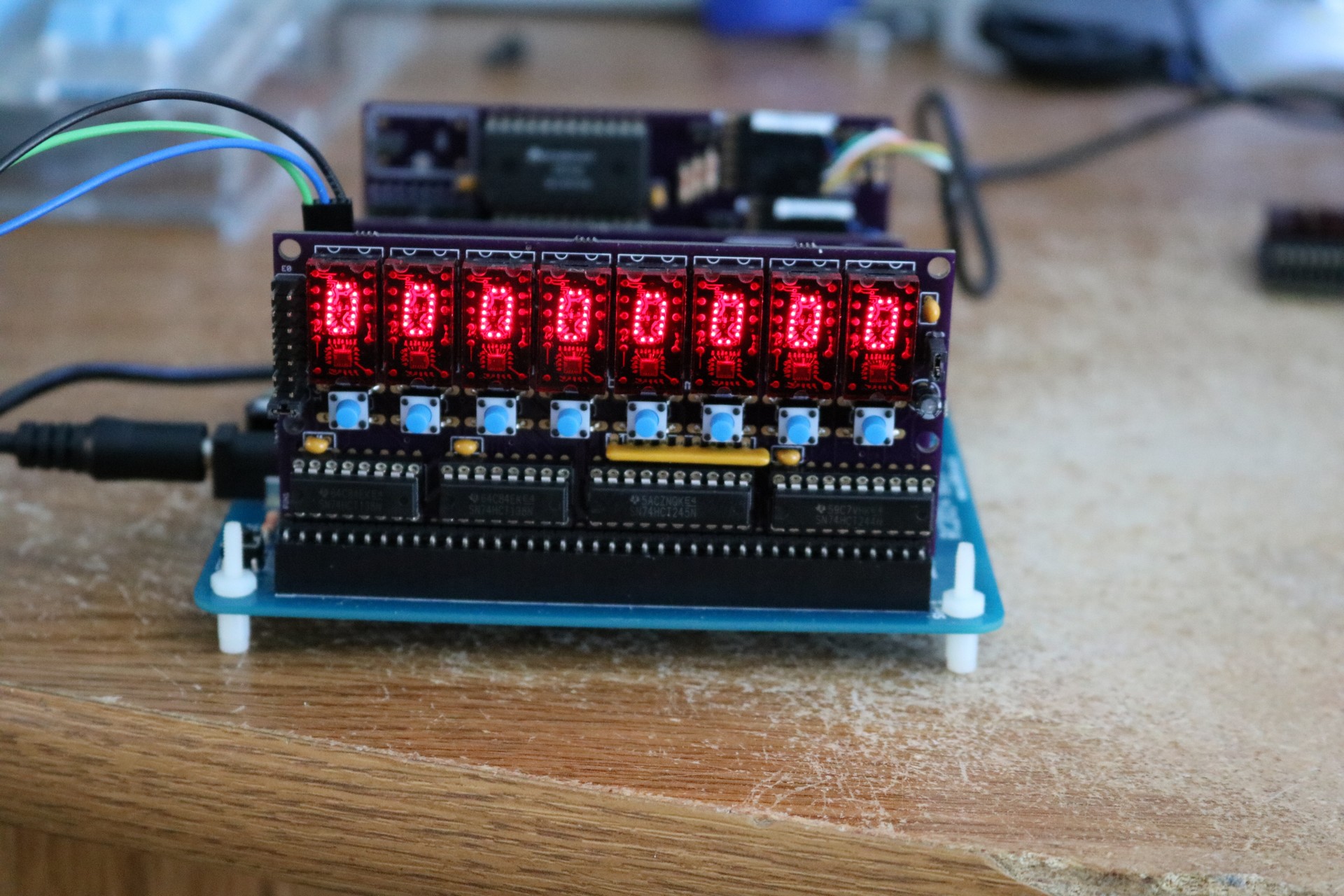
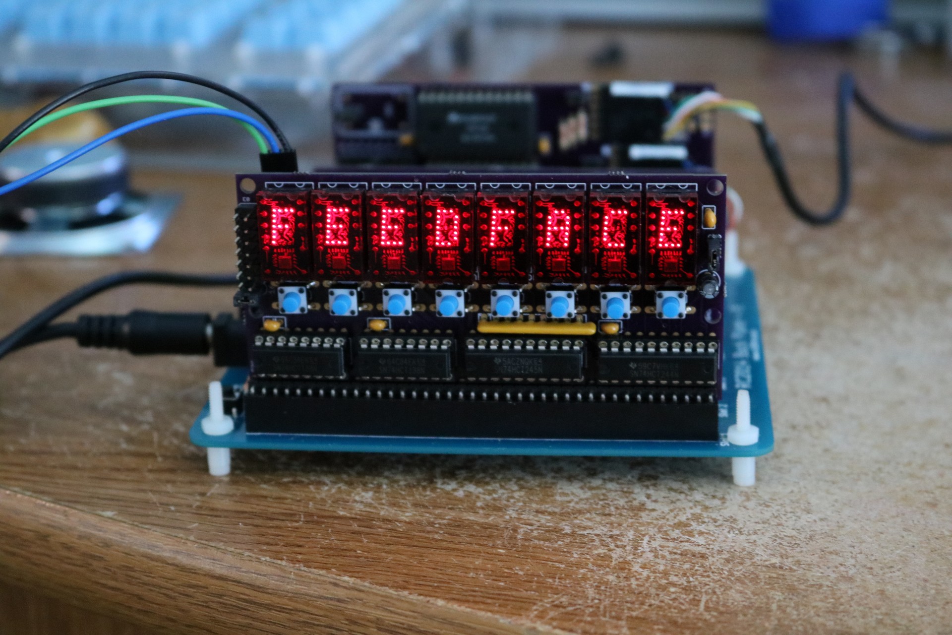
Here’s a couple of pictures of it connected and in-use:

RC2014 TIL311 Front Panel, All Zeroes

RC2014 TIL311 Front Panel, "FEEDFACE"

Power consumption

A word about power consumption. These TIL311 displays are electricity hogs. I measured the board at 690 ma power consumption. This is more than enough to make an unheatsinked 7805 burning hot and throw it into thermal overload. To resolve this problem, I switched out the 7805 regulator on my RC2014 backplane for a2.5A switching regulator from EZSBC. EZSBC has both a 1A and a 2.5A option available. They will drop right in place of a 7805.

Revision Thoughts

The first time I plugged the board in, I realized a few things I should have done differently. First, I didn’t make any provision to blank the displays. When you’re displaying something like a 6-digit (HH:MM:SS) clock, it’s convenient to turn off two of the digits. While you could just unplug two of the TIL311, it’d be far more convenient to turn them off. The second change I want to make is to enable the decimal points on the displays. It should be relatively easy to implement both of these changes using 74HCT374N latches, at the cost of additional complexity and a larger front panel board. I’ll probably make that change, as time and money permit.

Source code

There is a demo program in the source code repo at https://github.com/sbelectronics/rc2014.


Z80 Retrocomputing 7 – RC2014 DAC (Digital To Analog Converter)

$
0
0

I build a digital to analog converter for the RC2014:

[TODO: insert video here]

Digital to analog converters are useful for interfacing microprocessors to analog devices. They typically take a digital value of a fixed number of bits (in our case 8 bits) and convert it to an analog voltage or current. The DAC presented in this blog post will convert a value of 0-255 into a voltage from 0V to 5V.

Schematic:

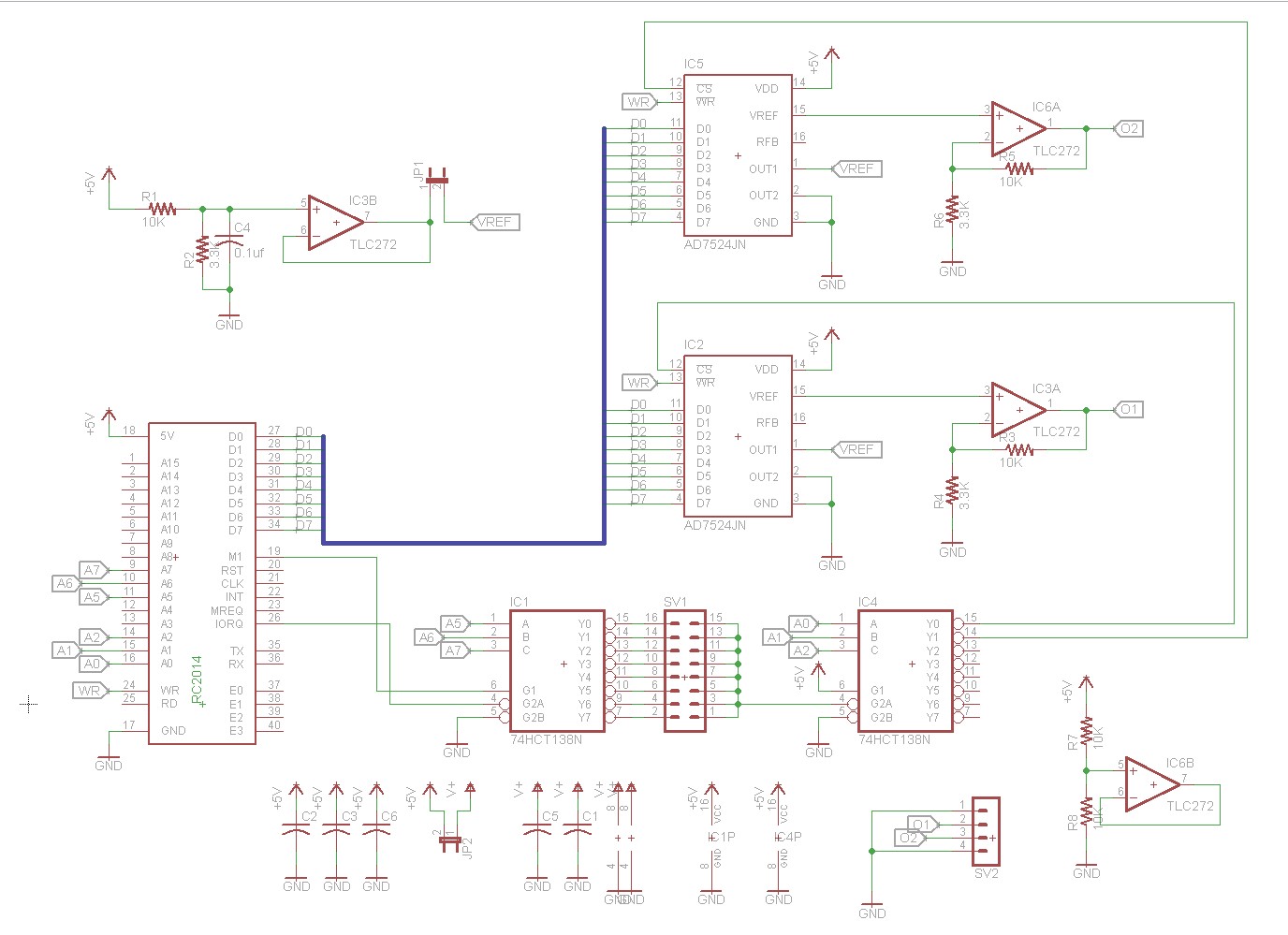
The schematic is shown below:

RC2014 DAC Schematic

The DAC I chose to use is an AD7524. It’s an 8-bit DAC, and has CS and WR pins, making it easy to digitally interface to an 8-bit microprocessor like the Z80. I also considered the DAC0808 (and even ordered some!) but the DAC0808 lacks an input latch, and would have necessitated adding additional chips to the circuit.

Address decoding uses a couple of 74HCT138 chips, just like most of the RC2014 peripheral boards that I’ve designed. One 74HCT138 allows MSB  selection of the IO port (00, 20, 40, 60, …) and the other uses the LSB to select which of the two DACs is enabled (00/01, 20/21, 40/41, etc).

I used the technique at http://www.waveguide.se/?article=a-simple-dac-using-the-tlc7524 to connect the AD7524 up to an op-amp to buffer the output. This seems sort of backwards, using the OUT1 pin as an input and the REF pin as an output, but that’s how the TLC7524’s datasheet describes voltage mode operation. The waveguide.se article contains a further refinement by Kevin Baker to divide the 5V down to a 1.25 reference voltage using an op-amp, and then multiply the resulting output value back up to 5V. It tried this technique, and it works with the caveat that not all op-amps are capable of rail-to-rail operation.

TheTLC272 op-amp that I used in the board can only output about 4V with a 5V Vcc. For this reason, I broke the op-amp’s Vcc output out to a header so that you could, for example, supply a 6V or 7V Vcc to get the full output range. An alternative would be to choose an op-amp with better rail-to-rail performance. I’m planning on trying out a TLV2462 at some point.

Implementation:

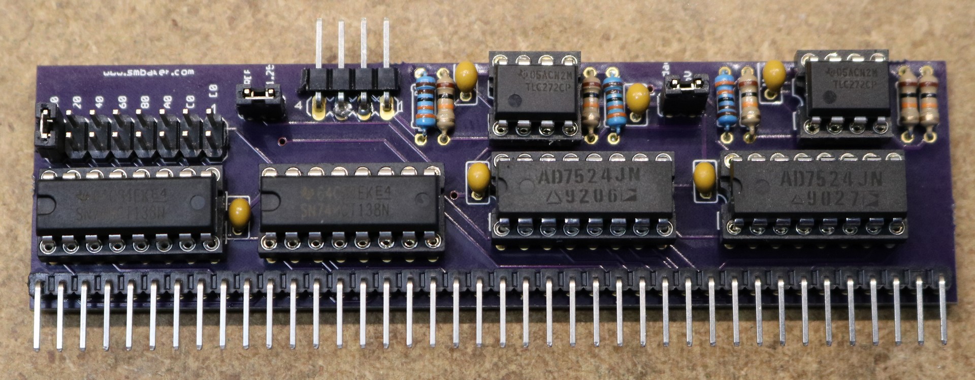
Here’s a picture of the completed DAC board:

RC2014 DAC, Assembled Board

This is one of those boards that actually worked right the first time.

Usage

Usage is pretty simple. Assuming the board is jumpered to the 00 address as shown above, just output the appropriate value to port 00 or port 01. For example,

REM set DAC A to 0V output
OUT 0, 0
REM set DAC A to 2.5V output
OUT 0, 128
REM set DAC B to 5V output
REM (note: using TLC272 op-amp with 5V Vcc, this will top out around 4V)
OUT 1, 255

Ordering a pc-board

As with most of my RC2014 boards, I’ve made it available on Osh Park. I don’t make any money off the Osh Park sales, and they only sell boards in multiples of 3, but it’s a way for you to get the pcboard to work with.

Order from OSH Park

Counterfeit/fake/justplainbad SP0256A-AL2 chips

$
0
0

All I wanted to do was build a speech synthesizer…

To make a long story short, I’ve ordered chips from three difference China eBay sellers, and have received three different sets of chips that don’t work right.

The first set of bad chips

Here’s the first one:

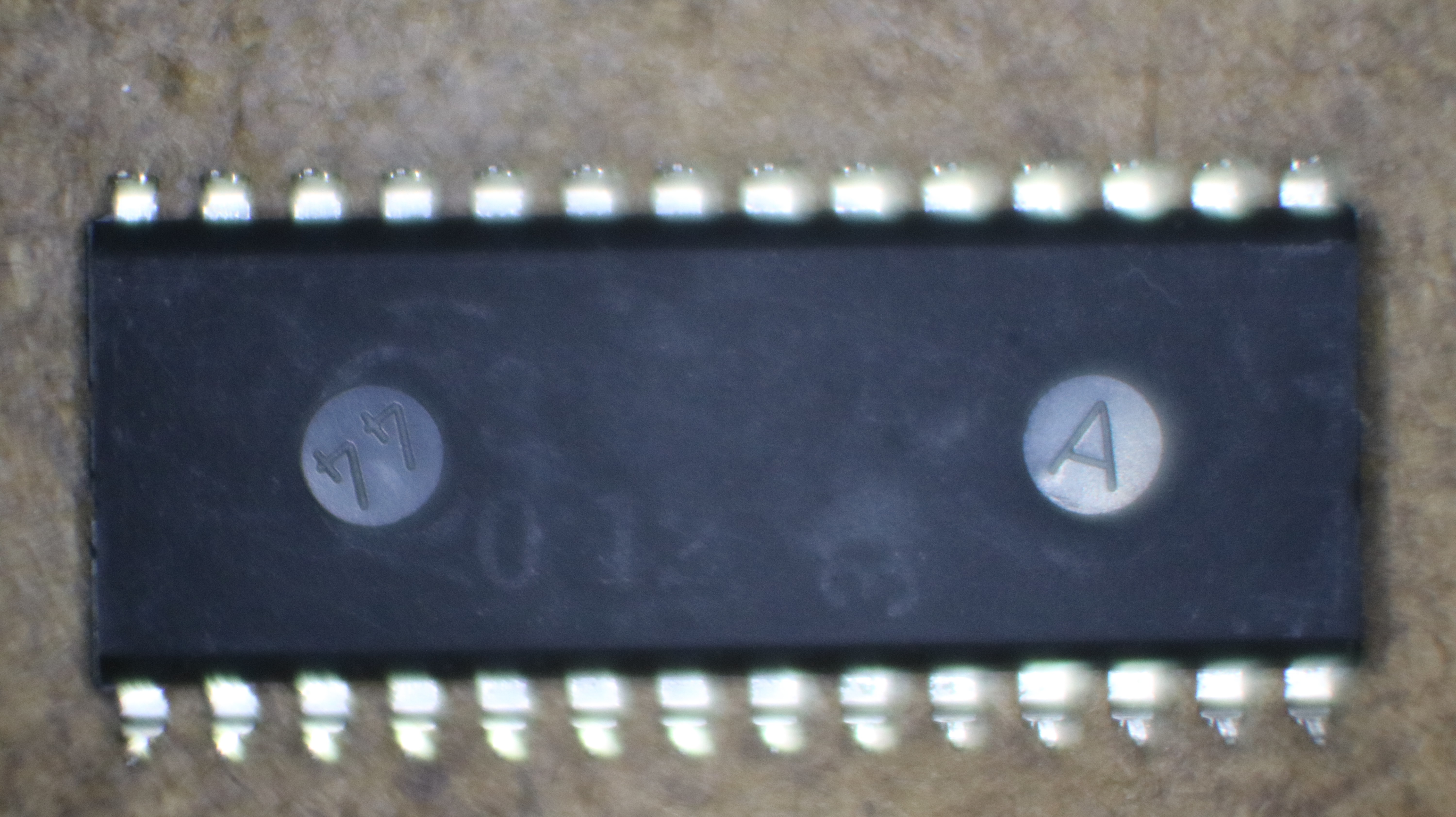
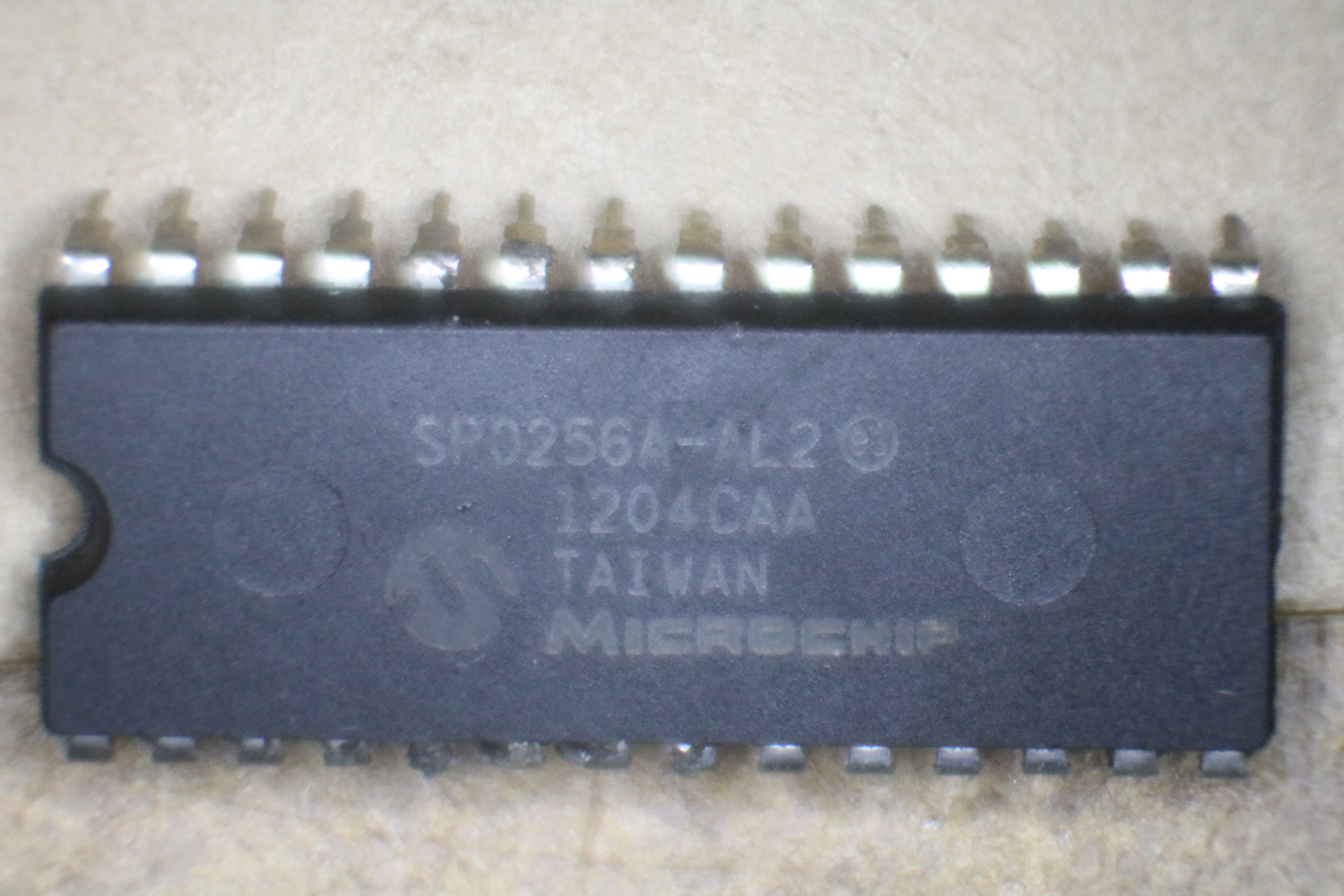
Bad SP0256A-AL2

This one actually turned out to be an SP0256A-012. The -AL2 version of the chip is programmed with phonemes and is capable of synthesizing any word in the English language (maybe other languages too). The -012 is programmed with a fixed vocabulary for the Mattel Intelovision game console and has the phrase “Mattel Electronics Presents” as well as a bunch of digits (“one”, “two”, … “thirty”, “forty”, …). It might be handy for something like a clock, but is pretty much useless for any other purpose.

Interestingly, the back size has an 012 faintly visible:

SP0256A-AL2, bad chip, back side

I’m not sure exactly what happened, whether GI actually made these chips with the wrong print on them, or whether they were printed correctly and some entrepreneur figured he could make more money by reprinting them.

The second set of bad chips

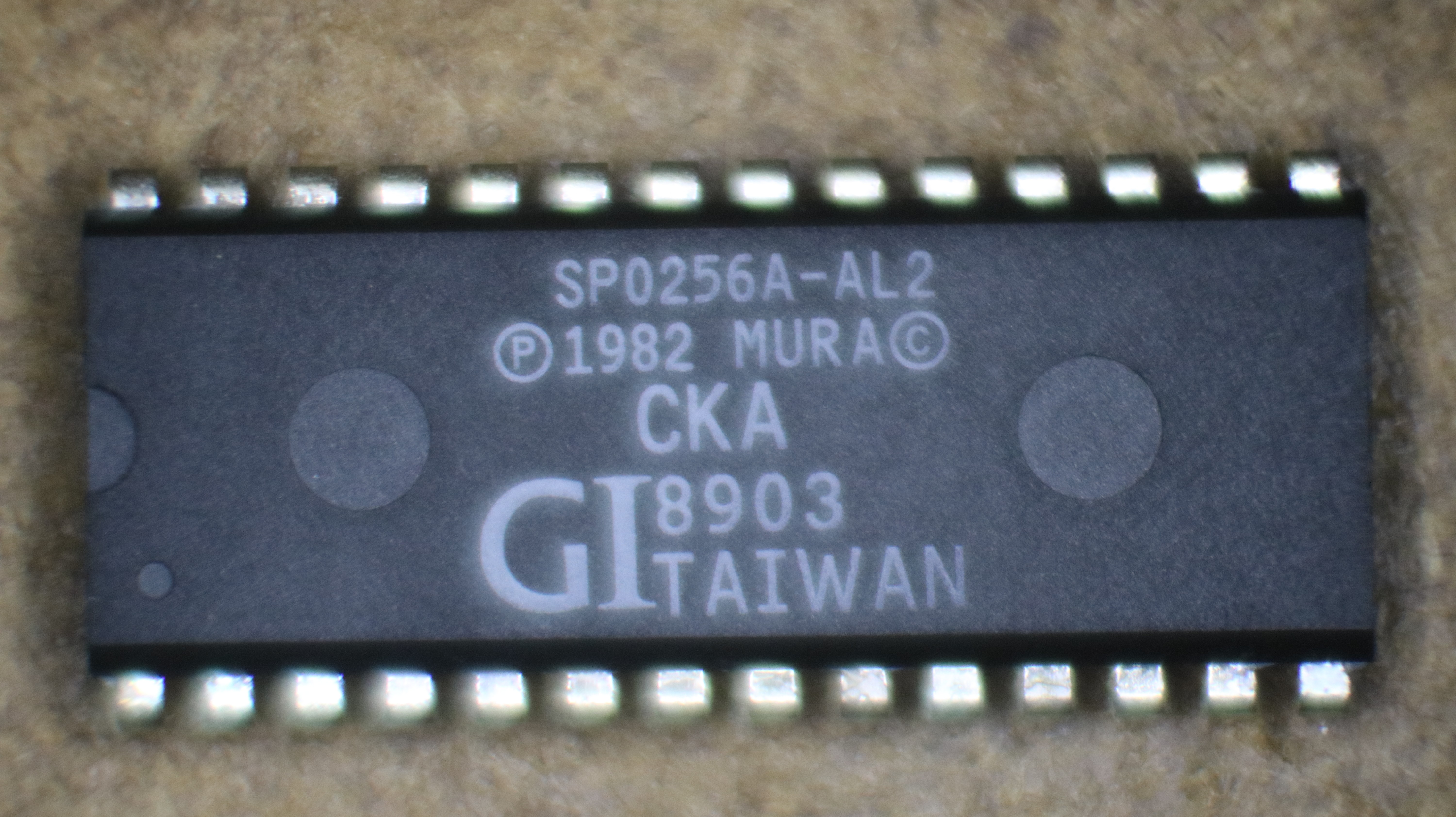
I decided to order more (Fool me once, shame on you. Fool me twice, shame on me). This time I chose a different seller, with chips that had a different manufacturer printed on them. Here’s a picture:

SP0256A-AL2, bad chip number 2

Unlike the previous ones, these ones don’t output any speech at all. There is some noise that comes out of the output pin, and that noise varies according to what is on the address and data buses, even when the chip select input is not triggered. So it kinda makes annoying noise all the time.  It also glitched my RC2014 so that it wouldn’t run (probably by outputting signals to the address, data, or control buses).

I suspect these are just some random 28-pin IC that someone reprinted. I suppose it would be an interested exercise to apply to signals to the fake chips and use a logic analyzer to try to figure out what it’s actually doing, and determine that the chips actually are.

The third set of bad chips

These ones appear similar to the second set. Same manufacturer marking (“Microchip”). The second line is 11263UK instead of 1204CAA. I’m not sure if that’s supposed to be a date code, or something else. Maybe someone who knows can let me know.

In addition to generating weird noises instead of speech and glitching my RC2014 so that it wouldn’t work, merely plugging the cursed IC in seemed to damage two MC68B50 serial IO chips that I had in an adjacent slot on the RC2014. They’re just kinda wonky now. I suspect the fake SP0256-AL2 and the MC68B50 put conflicting outputs on the data bus at the same time, and this caused damage to the MC68B50. Maybe it damaged the fake SP0256A-AL2 as well. Who knows.

The fourth set (good chips?)

I’ve ordered yet another set of chips, this time from a US seller who has a reputation for selling quality non-counterfeit speech chips. They should be here in a few days. I’ll report back as to their functionality.  I’m keeping my fingers crossed that they will be good. They cost $30 each, as opposed to the $4-$9 that the chips from China did.

Z80 Retrocomputing 8 – Speech Synthesizer for RC2014

$
0
0

I built a speech synthesizer board for the RC2014

TODO: Insert video here

The speech synthesizer IC that I chose is the SP0256A-AL2. One of my reasons for choosing it was that it seemed plentiful on eBay. They’re all fakes though, every damn one of them on eBay, so far as I can tell. :( Fortunately, there is a reputable seller here in the states, www.speechchips.com.

Schematic

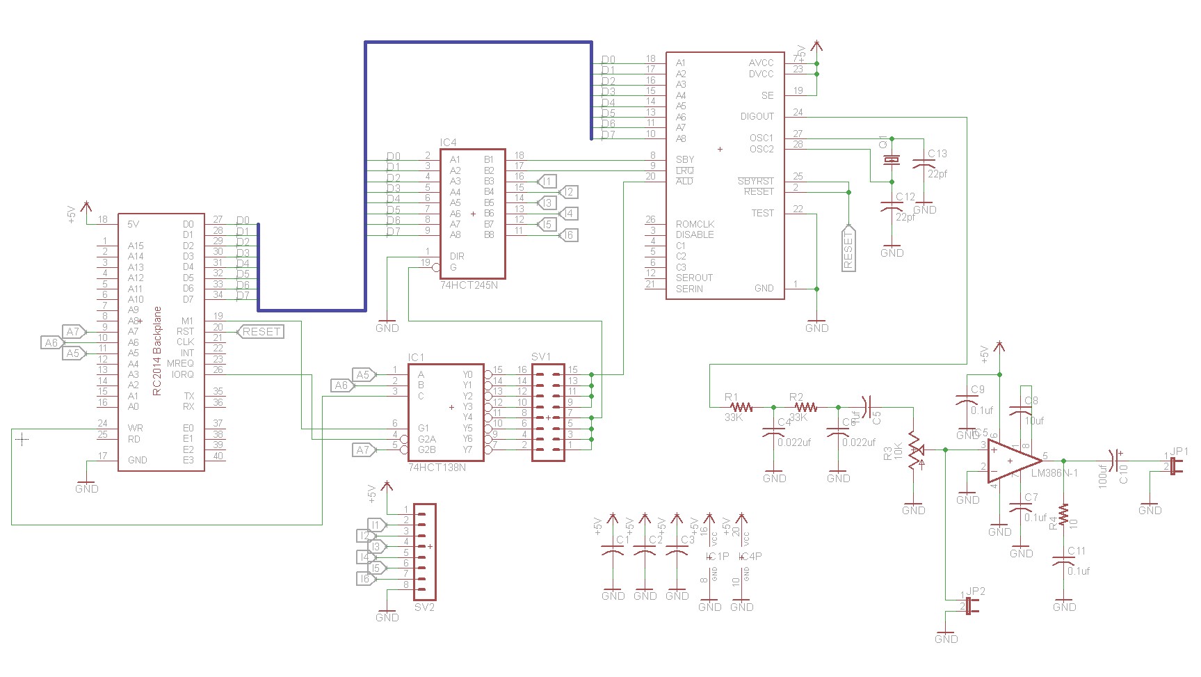
Here is the schematic for the speech synthesizer board:

RC2014 Speech Synthesizer, Schematic

The circuit is relatively straightforward. The SP0245A-AL2 is connected to the data bus via D0-D7. There’s an active low signal, ALD, that causes the SP0256A-AL2 to load whatever is on the data bus, and we connect that to a 74HCT138N for address decoding. The SP0256A-AL2 provides two status signals back to the CPU, I tied them to the data bus using a 74HCT245N. Writing to the port selected on the 74HCT138N will write to the synthesizer, and reading from that same port will read the status back.

Using the chip involves writing a phoneme, and then polling for the chip to become ready before writing the next phoneme. An alternative implementation would be to use an interrupt handler. I didn’t want to worry about sharing interrupts between the speech synthesizer and the serial port, so I went with the polling solution.

Implementation

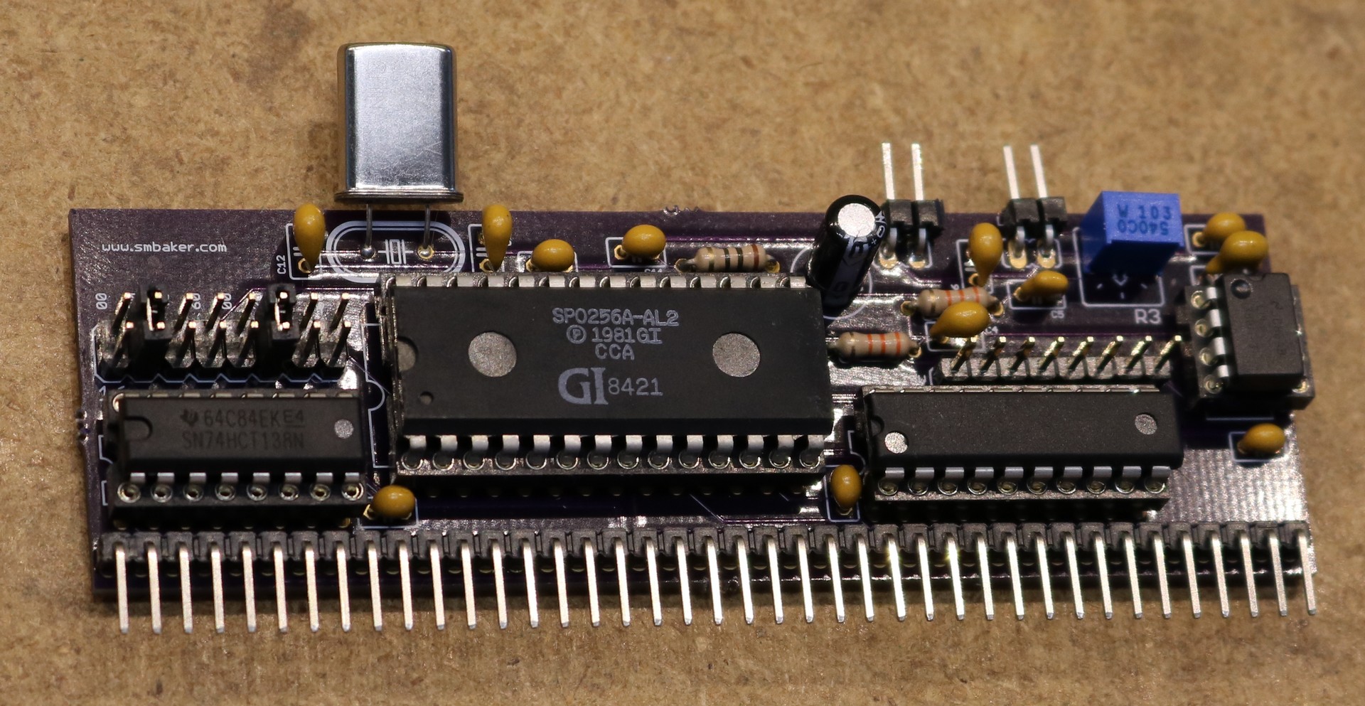
Here’s a picture of the pcboard.

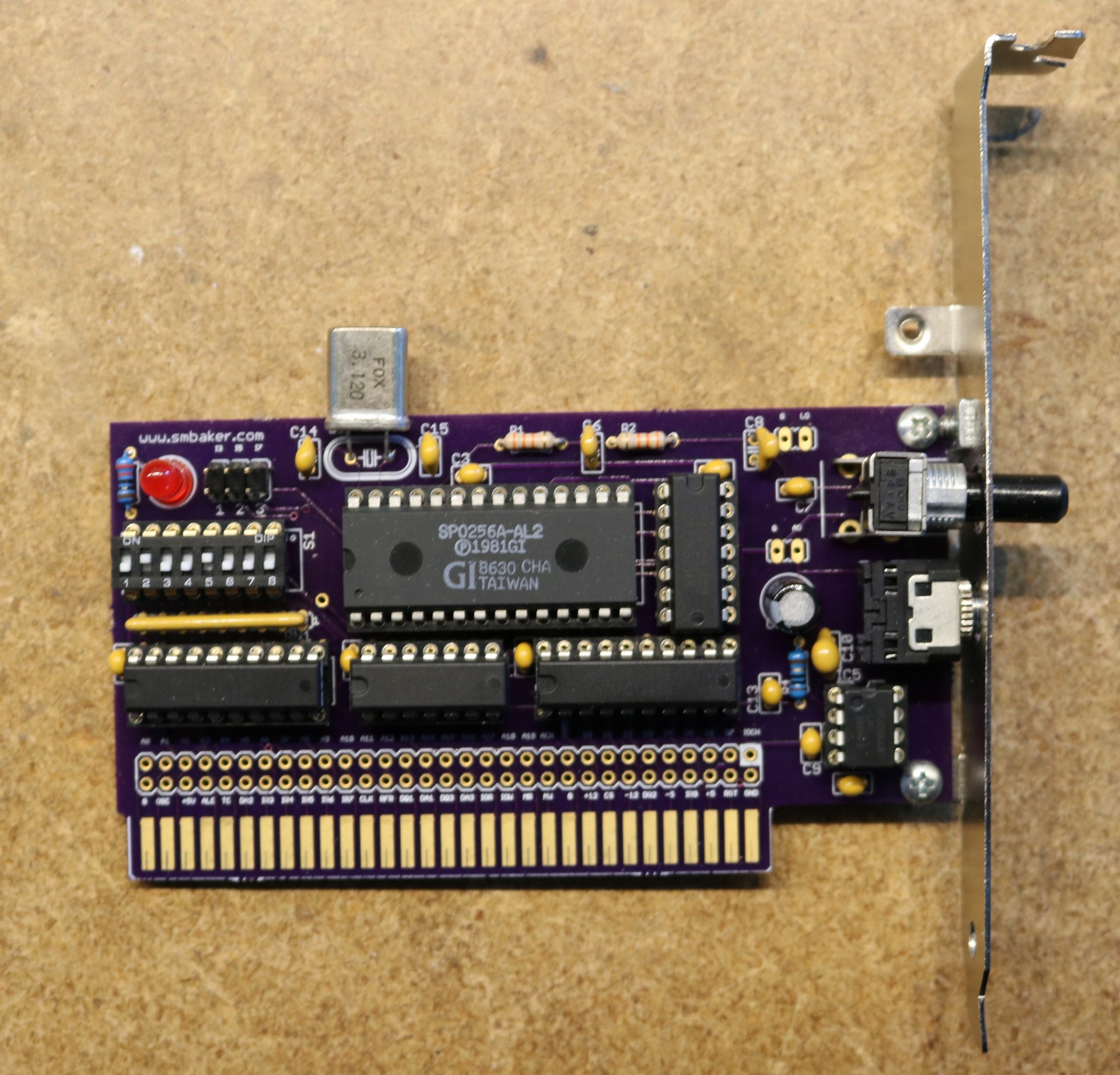
Speech Synthesizer for RC2014, Assembled

Source Code

You can find the source code in my repo at www.github.com/sbelectronics. There’s a demo program that says a couple of phrases and is able to recite the lyrics to Daisy Bell.

Ordering the pcboard

You can find the pcboard on Osh Park. You’ll have to buy them in three quantity because that’s the way Osh Park sells them.

Order from OSH Park

Z80 Retrocomputing 9 – CTC and dual serial ports for RC2014

$
0
0

In this post, I add a Z80 CTC (counter-timer) and SIO/2 (serial IO) to the RC2014

If you haven’t read my other Z80 retrocomputing blog posts yet, then please start with the first one, Intro to Z80 Retrocomputing, for an overview of the RC2014 platform.

Motivation

All I wanted to do was connect a GPS module to the RC2014… This turned out to be much more difficult than I anticipated.

I started by designing a dual 68B50 serial board, but I neglected to pay attention that the GPS module I chose (UP501) operated by default at 9600 baud. While you can configure it to operate at additional baud rates, you have to send the configuration command at the power-up default, which is 9600 baud. The 68B50 can be configured with a clock divider of 1, 16, or 64. With the RC2014’s system clock, that allows us to easily select 115,200 baud by using a divider of 64. However, there’s no way to easily select a baud rate that is less than 115,200 baud.

I explored a number of alternatives to adding additional clock chips and dividers. This seemed like a lot of work and special-purpose complication, especially if I wanted to be able to control the baud rate using software. Ultimately I decided to use the Z80 CTC. The CTC offers 4 independent counter/timers. Three of them have external outputs, which we can connect to our serial chip to use as a baud rate reference.

68B50 vs SIO/2

My original solution was a dual 68B50 board. For whatever reason, this proved very unreliable. It was sensitive to which slot it was plugged into the RC2014 backplane. It had to be right next to the CPU, or occasionally it would do weird things like drop characters or fail to reset properly. I spent a fair amount of time trying to debug my dual 68B50 board, and ultimately decided on using the SIO/2 instead.

The SIO/2 is a dual serial chip. It is far more complex than the 68B50, offering different operating modes and fancier interrupt support. For configuration there are eight different write registers and three different read registers. One advantage is that one SIO/2 chip yields two serial ports, whereas I would have needed two 68B50.

CTC Board Design and Implementation

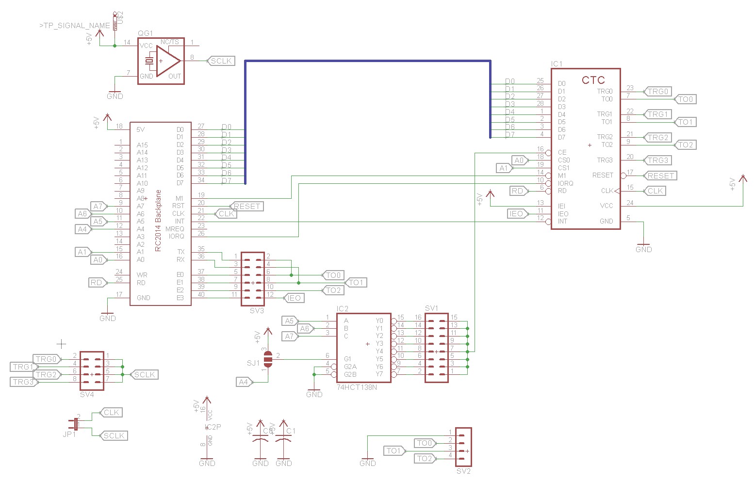
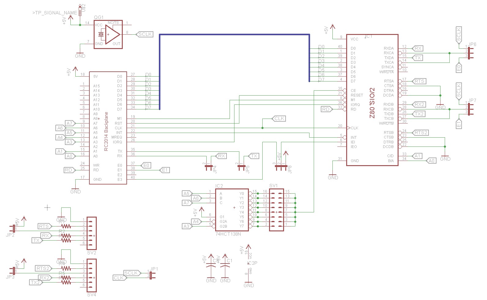
Here is the schematic of the CTC board

RC2014 CTC board Schematic

The schematic is fairly straightforward. There’s a 74HJCT138N for address decoding, which is used as a chip select for the CTC. I’ve brought the CTC’s signals out to a couple of places. TO0, TO1, and TO2 (the outputs) are brought out to a header at the top of the board and to some jumpers that let you easily connect them to the RC2014 backplane’s extra pins. TRG0, TRG1, TRG2, and TRG3 (the triggers) are brought out to a dual pin header block that allows you to easily connect them to either an on-board oscillator or (if the on-board oscillator is not installed) to the system clock. SJ1 is a jumper that allows you to restrict addressing to when A4 is high. This will let you put the board at 10,30,50,70,90,B0,D0 instead of on 00,20,40,60,80,A0,C0,E0 like my other boards. My plan is to put the board at 0×90 so that it shares the 0×80-0×9F address range with the SIO.

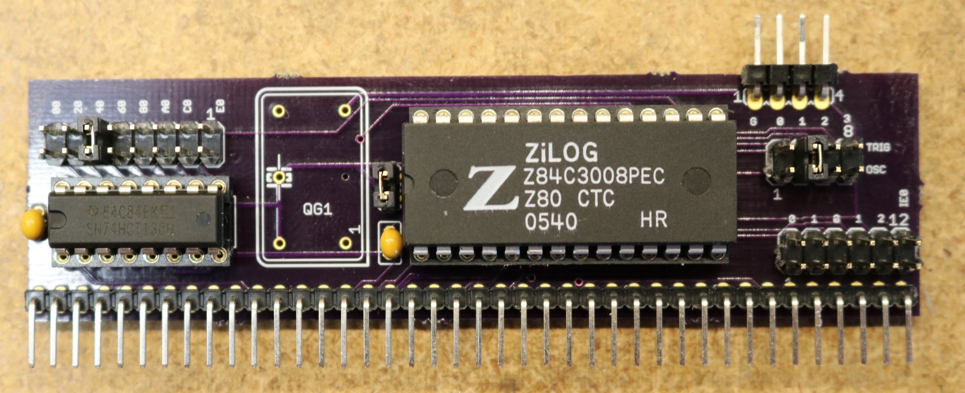
Here is my completed CTC board:

RC2014 CTC Board, Assembled

As you can see, I’ve left the footprint for the crystal unpopulated. The jumper to the right of the crystal footprint passes the system clock over to the TRIG/OSC jumper block to the right of the CTC chip, where I’ve jumpered it to the channel 1 trigger.

SIO Board Design and implementation

Here is the schematic of the SIO board:

RC2014 SIO/2 board schematic

This is also a fairly straightforward board. We again have a 74HCT138N for address decoding that allows us to put the board on 00,20,40,60,80,A0,C0, or E0. The serial ports are brought out to a pair of 6-pin headers that allow you to easily connect FTDI cables or other devices like a GPS. I opted not to install a MAX232 driver on-board. If you really want a 9-pin serial port, then a MAX232 can be installed externally.

There are two jumpers, JP6 and JP7 that allow you to either select the system clock as the clock source, or get clock from one of the RC2014 backplane’s extra pins. The idea is that a CTC pin will be brought out to E1 on the CTC board, and then picked up on E1 for the SIO board to allow us to set custom baud rates. The TX and RX pins can be jumpered to the backplane as well. Finally, there is a jumper for the interrupt mode that allows you to either use 5V (interrupts allowed all the time) or to connect the interrupt pin to E3, where it could in theory be connected to the CTC board. For simple implementation, I enable the interrupts all the time, but the CTC and SIO do have a more sophisticated mechanism where they can generate interrupt vectors that identify the device that generated the interrupt.

There is an optional oscillator footprint that allows you to use a custom oscillator, and a jumper to use the system clock instead of the custom oscillator.

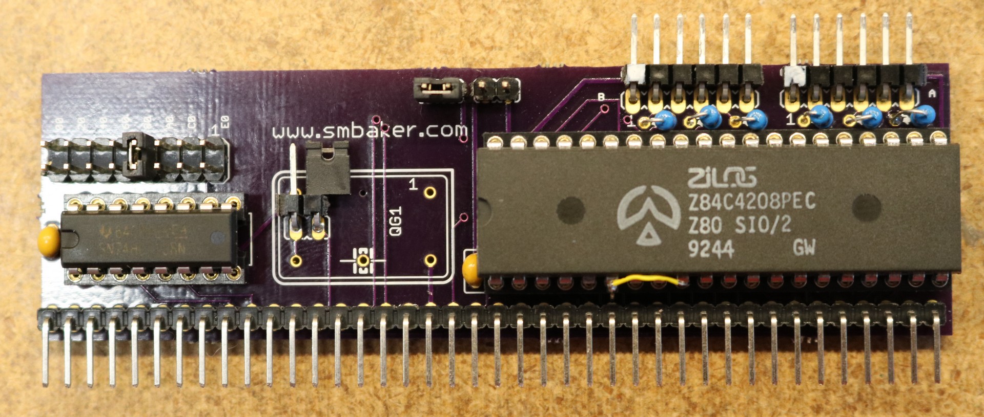
Here is the completed board:

RC2014 SIO board, prototype

As you can see, this board has a few … imperfections … I mistakenly wired the IEI pin to GND when it should have been wired to 5V, hence the yellow jumper wire. I also didn’t have any provisions for using separate clocks for ports A and B (not visible, but there is a cut trace under the SIO chip and a piece of yellow wire on the back to deal with this). These issues have been corrected in the schematic, and I’ll soon be sending off for a replacement board.

Programming the CTC as a baud rate generator for the SIO/2

My first attempt was to use the CTC in timer mode. This seemed relatively simple to me, I would take the system clock, prescale by either 256 or 16, and then setup the time constant for the final division to yield the appropriate baud rate. The SIO/2 would be configured to divide by 1. Here are my calculations:

CPU Frequency = 7,372,800 Hz.

Baud Prescaler Time Constant
1200 256 24
2400 16 192
9600 16 48
19200 16 24
38400 16 12
57600 16 8
115200 16 4

Unfortunately, the above scheme didn’t work very well. Sometimes it would work, but sometimes the SIO/2 would end up out of sync with the incoming serial stream and output occasional splotches of gibberish. After some experimentation, I found that my SIO/2 was unreliable whenever the clock mode was set to X1. The same thing would happen when I tried to use my 68B50 with an X1 clock divider. I’m still a little bit confused at this; my reading of the data sheets led me to believe this would work just fine. Maybe it comes down to quality of implementation and my PCB layouts aren’t quite clean enough for the X1 mode.

I did find that the SIO/2 would work perfectly if the clock mode was set to X16. This means we have to output a rate from the CTC that is 16 times higher than our baud rate. For a baud rate of 115,200 that would mean outputting a timer rate of 1,843,200 Hz. Since the CTC always selects a prescaler (either 16 or 256) in timer mode, a 7.3728 MHz system clock is insufficient to produce a timer rate of 1,843,200 Hz.

This led me to try operating the SIO/2 in counter mode with an external trigger. Counter mode works much like timer mode, but it counts external pulses via the trigger input. The advantage to counter mode is that the X16/X256 prescaler is not forced upon you. We can feed the system clock into the trigger input, and then use timer mode to output the baud rate we want.

Baud Timer Rate Time Constant
1200 19200 96
2400 38400 48
9600 153600 24
19200 307200 12
38400 614400 6
57600 921600 4
115200 1843200 2

This worked perfectly. I was able to read from my GPS without constant weird splotches of high-ascii gibberish.

If you check my math in the above table, you’ll notice the time constants are half of what you’d expect them to be. This surprised me, and I think I found the answer in the CTC data sheet: “Although there is no setup time requirement between the triggering edge of the External clock and the rising edge of Φ (Clock), the down-counter is not decremented until the following pulse“. Since I have the trigger connected to the system clock, it’s counting every other trigger pulse.

Modifying RC2014 Basic

I started with Grant Searle’s Z80 SBC modifications to Nascom Basic. A link to Grant Searle’s ZIP file containing source code is here. The changes I made are the following:

  1. Use an SIO/2 instead of a 68B50
  2. Modify interrupt handler, TX, and RX functions for the second serial port.
  3. Add a BAUD rate function to set the baud rate.
  4. Add four new BASIC keywords: ISER, OSER, RSER, and BAUD.

The new basic keywords function as follows:

  • ISER(x) – read a character from serial port (x=0 or 1)
  • RSER(x) – check readiness of serial port (x=0 or 1)
  • OSER x,y – output character Y to serial port X (x=0 or 1)
  • BAUD x,y – set baud rate on port X to Y (x=0 or 1, y=1 for 1200, 2 for 2400, 9 for 9600, 115 for 115200)

Here is a sample program that reads all characters on the second serial port and writes them to the first serial port.

10 REM check port 1
20 IF RSER(1)=0 GOTO 50
30 X=ISER(1)
40 OSER 0,X
50 GOTO 10

Wiring it all up

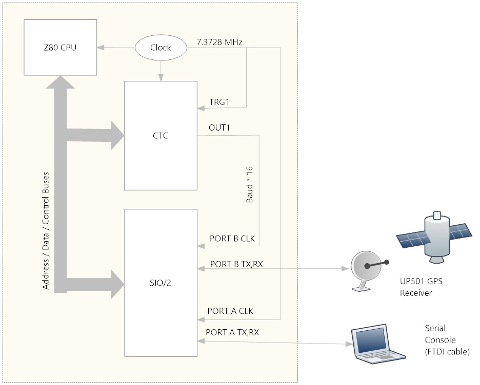
Here’s a diagram of how everything is connected:

CTC and SIO diagram

Source code

As usual you can find the source code in my github repo at http://www.github.com/sbelectronics.

PC-Board ordering:

As usual, you can find them on osh park:

CTC Board

Order from OSH Park

SIO/2 Board

Coming soon…
Nixie Calculator Update – PCB availability, source code, design notes

$
0
0

The nixie tube calculator project was not funded on kickstarter, and I recall some time ago promising to make the boards and other resources that I used for constructing the prototype available. Well, it’s taken a while but I’ve finally got around to it.

I’ve made the boards available on Osh Park, which is the same site I ordered my prototypes from. Osh Park always sells boards in quantity of 3. To build the same calculator I built as the prototype, you’ll need 2 nixie display boards, 2 4×4 keypads, 1 2×2 keypad, and one power supply board. You’ll also need a raspberry pi. Since the boards are sold in quantity three, you’ll generally have at least one board leftover. Put it to good use in some other project. ;)

Use these ordering links at your own risk. I make no money off of the Osh Park sales, and I accept no responsibility for the quality of the board or the accuracy of the layout or the proper functioning.

The link to the original blog post on the calculator is here: http://www.smbaker.com/nixie-tube-calculator-powered-by-a-raspberry-pi

Nixie Display board

Order from OSH Park

4×2 keypad

Order from OSH Park

4×4 keypad

Order from OSH Park

High voltage power supply

Order from OSH Park

Source code

The source code can be found at my github repository at https://github.com/sbelectronics/nixiecalc

Wiring the calculator

The I2C bus is daisy chained from one board to the next. A short cable connects the raspberry pi to the leftmost 4×4 keypad. There are five wires: 3.3V, SDA, SCL, G, and 5V. Right angle headers are used to connect that keypad to the middle 4xz4 keypad, and right angle headers are then used to connect the middle keypad to the rightmost 4×2 keypad. A short cable then goes from the rightmost 4×2 keypad to the rightmost nixie display board. Right angle headers connect the two nixie display boards together.

Setting the addresses of all of the I2C devices is important. Each board (keypad, nixie display board) includes two or three jumpers for this purpose. There can be eight devices on the I2C bus. Each display board consists of two devices. Each keypad has one device. This adds up to a total of 7 I2C devices.

TODO: add picture of jumper configurations for keypad boards and nixie display boards.

The power supply board includes a 5V output for powering the raspberry pi and the other boards. I spliced the 5V supply into the 5-wire cable that goes from the pi to the leftmost keypad.

A single high voltage wire goes from the power supply board to the rightmost nixie display board. The high voltage is daisy changed from the rightmost nixie board to the leftmost using right-angle headers.

There isn’t much space between the leftmost keypad and the rightmost keypad and the case edges to plug in the cables. For this reason, I made some right-angle adapters by soldering a male angle header to a female straight header.

The case

The case for the calculator was fabricated by Ponoko.It is constructed of laser cut acrylic and uses 4-40 fasteners.

TODO: Figure out if there’s a way to share it on the Ponoko site, provide material details.

Z80 Retrocomputing 10 – RC2014 CompactFlash board

$
0
0

In this post, I implement a compactflash adapter for the RC2014

[TODO: Insert Video Here]

If you haven’t read by first blog post on the RC2014, please start there as it will provide background information, including where I purchased the kit from.

Purpose

If I think back to my first computing experiences, there was usually some form of storage. In my case, I had a TRS-80 COCO, which I started with a cassette drive and then eventually evolved to a 5 1/4 floppy. For the Z80, it turns out that a CompactFlash card is surprisingly easy to interface. I used a couple of websites to help with this, including Grant Searle’s CPM Z80 computer and Retroleum’s 8-bit CompactFlash Interface.

Adding compactflash will allow us to expand the things we can do with the RC2014. With a bit of work it should be feasible to save and load data from a basic program. We can run the CP/M operating system.

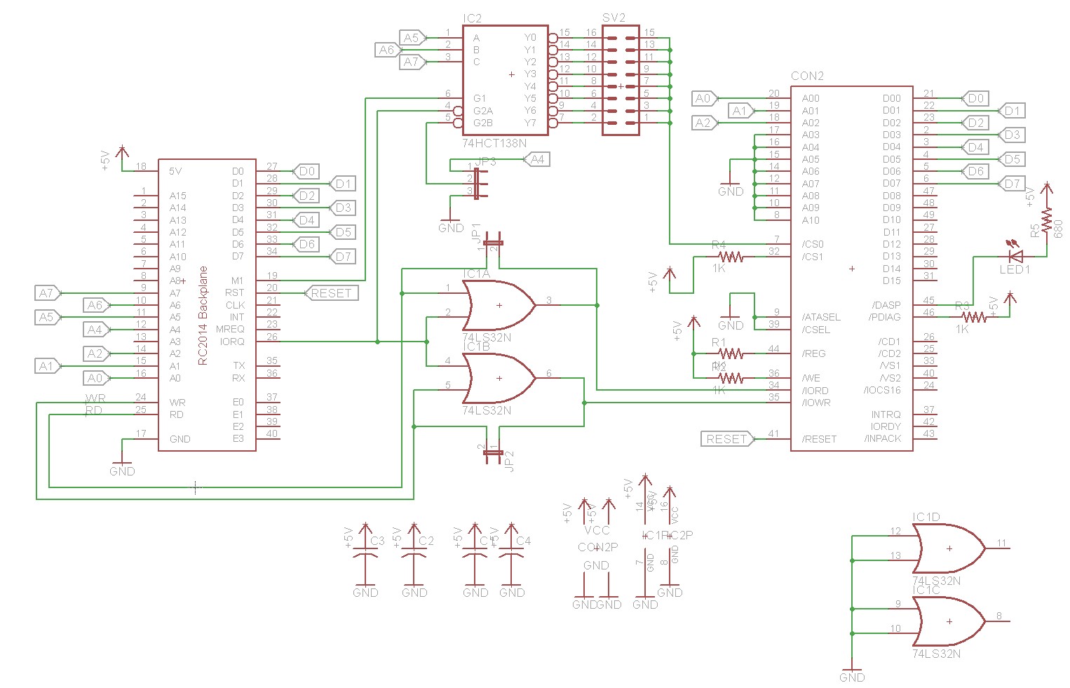
Schematic and Design

The schematic of my prototype is shown below:

RC2014 CompactFlash Board, Schematic

As you can see, we have the typical 74HCT138N for address decoding. This allows us to put the CompactFlash card on any of eight addresses: 00, 20, 40, 60, 80, A0, C0, or E0. In my example code, I have placed it at E0. There’s a Jumper, JP3, that can be used to connect A4 to one of the active-low inputs of the 74HCT138. This allows you to set the 74HCT138 be active for only 10h of address space instead of 20h of address space like my other boards. There’s really no good reason not to jumper it that way.

The 74HCT138’s output is tied to the /CS0 pin of the compact flash card, and is used as chip select for the primary bank of compactflash card registers. The compactflash also has a secondary bank, selectable by /CS1. We don’t need those, so /CS1 is tied to +5V. Either data pins are connected from the Z80 to the CF dard, D0-D8. There are three address lines, A0-A2. This allows us to select any of eight registers on the compactflash card, which are all the registers we need to implement the 8-bit interface. There are read and write pins, /IORD and /IOWR that are connected to an OR gate that combines the Z80’s IOREQ signal with the  Z80’s RD and WR signals. There’s a /RESET pin, which we hook up to the same reset line that drives the rest of the RC2014.

IC1 is a quad OR gate that combines IOREQ and RD to form IORD and combines IOREQ and WR to form IOWR. Since IOREQ, RD, and RW are active low, ORing IOREQ and RD is an effective way to generate an active low signal that is only low if both IOREQ and RD are both low. Two gates of IC1 are unused and their inputs are grounded.

There are also a number of pins that I tied to ground. A03-A10 are addressing pins that we don’t need for 8-bit mode. /ATASEL forces the compactflash into True ATA mode. /CSEL has something to do with master/slave cable-select. /REG and /WE aren’t used in True IDE mode and are pulled to 5V. /PDIAG is the pass-diagnostic signal. I’m not sure exactly what that’s for, other than it’s something to do with master/slave mode and we’ve pulled it to 5V.

/DASP can be used to implementing a busy LED that will show you when the drive is busy. This also seems to serve some kind of purpose in the master/slave protocol.

The rest of the pins are left floating.

Hardware Implementation

A picture of my prototype is shown below:

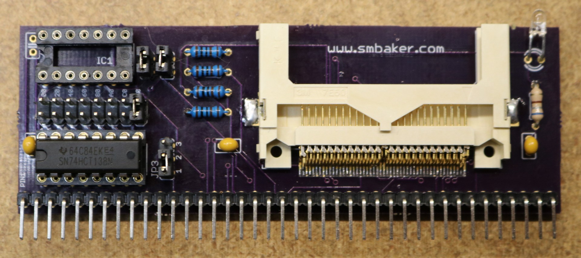
RC2014 compactflash adapter

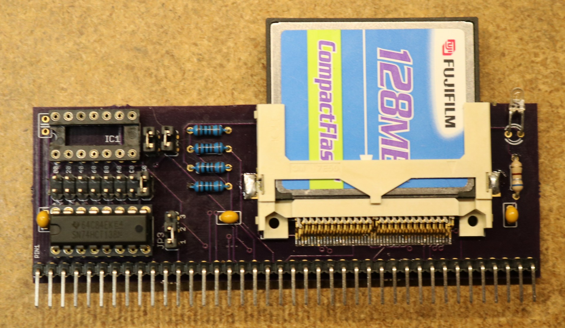
rc2014 compactflash board, with card installed

I thought I was going to be clever, and omit the OR gate (IC1 in the schematic) that generated IORD and IOWR signals by combining RD/IOREQ and WR/IOREQ. I added some jumpers that supplied RD and WR instead. In fact, I originally wrote up this blog post thinking that approach was working and IC1 could safely be left out. Turns out I was wrong, and CP/M became unstable when reading large files. I haven’t had time to research why yet, and I’m guess it’s either some quirk of timing or some quirk of signal quality. Until I figure out why, you should assume that IC1 needs to be populated, and the two jumpers to the right of IC1 removed.

The CompactFlash socket itself is a surface mount part, digikey part number 3M155880-ND. They are about eight bucks each, and I’d suggest ordering a spare just in case there are any mishaps while soldering it. The pins are spaced relatively closely together, so it can be a bit of a beast for someone who is not familiar with SMD work. I used my Aoyue 861A++ rework station to do the soldering. I started by laying down a continuous bead of solder paste, then used the hot air iron on it, then used desoldering braid to clean up any bridges. There are lots of techniques for soldering SMD devices, some even using a traditional iron (drag soldering). You might want to practice on something else before working on the relatively expensive (about 8 bucks) and delicate compactflash socket. After soldering inspect with a microscope or magnifier to make sure there are no bridges.

Compatible CompactFlash Cards

I obtained a number of CF cards from eBay. I concentrated mainly on getting 128 MB and 64 MB cards, as those are the maximum and minimum usable by Grant Searle’s CPM prototype. Successful cards included Fuji 128MB, PQI 128MB, Wintec 128MB, Cisco 64MB (these Cisco cards seem really plentiful on eBay), and Mr. Flash 128MB.

A Viking 128MB card behaved oddly. It took this card approximately 30 seconds to become not-Busy after power-cycle. I believe this has to do with some issue with the master/slave protocol and that it was timing out waiting for the slave. Probably something to do with the /DASP or /PDIAG pins. The busy LED also didn’t work properly, staying on the whole time. If you encounter a Flash card that seems to misbehave, try giving it a good 30 seconds to see if it’s this same issue.

I also had a Sandist 64MB card what was either outright defective, or that I managed to damage. I can’t get it to work in either the RC2014 or my windows PC.

Programming

Using the compactflash card is relatively straightforward. The retroluem site linked above explains some of this a little more clearly than I do, and documents how to read the Disk ID, which can be a useful way to verify the card is working.

Keep in mind that when I say “register x” that’s relative to the port address that you’ve selected for the compactflash card. If you put it as 0xE0 like I did in my examples, then register 0 is as 0xE0, register 1 is at 0xE1, …, register 7 is at ox E7.

Setup:

  • read register 7 until the busy bit (0×80) is unset
  • write 1 to register 1
  • write 0xEF to register 7
  • write 0×82 to register 1
  • write 0xEF to register 7

0xEF is the “set feature” command. Feature 1 enables 8-bit mode. Feature 0×82 disables any write caching. You should do this whenever the compactflash is reset or power cycled.

Read a sector

  • read register 7 until the busy bit (0×80) is unset and the ready bit (0×40) is set
  • write 1 to register 2, to set the sector count to one sector
  • write bits 0..7 of the block address to register 3
  • write bits 8..15 of the block address to register 4
  • write bits 16..23 of the block address to register 5
  • take bits 24..27 of the block address, or them with 0xE0, and write to register 6
  • write 0×20 to register 7. This is the “read sectors” command.
  • read port I7 until the busy bit (0×80) is unset and the DRQ bit (0×08) is set
  • read 512 bytes from register 0

Write a sector

  • read register 7 until the busy bit (0×80) is unset and the ready bit (0×40) is set
  • write 1 to register 2, to set the sector count to one sector
  • write bits 0..7 of the block address to register 3
  • write bits 8..15 of the block address to register 4
  • write bits 16..23 of the block address to register 5
  • take bits 24..27 of the block address, or them with 0xE0, and write to register 6
  • write 0×30 to register 7. This is the “read sectors” command.
  • read port I7 until the busy bit (0×80) is unset and the DRQ bit (0×08) is set
  • write 512 bytes to register 0

I originally implemented this entirely in basic (see cf.bas in my github repo). Reads worked fine, but the writes did not work. I think what happened was that I was writing to the card too slowly, and the write operation was timing out. RC2014 basic is a very slow way to try to do peripheral IO. Assembly is much, much faster.

My second implementation was to modify the basic ROM to include three new statements: DINIT, DREAD, and DWRITE which handle initialization, read, and write. The read and write transfer the contents of a sector to a buffer in RAM, which can then be peeked and poked by the relatively slow basic interpreter. This is demonstrated by cf_dbas.bas in my github repo. Extensive modifications to the Basic ROM were necessary, and I will make patches available in the github repo, so that you can assemble your own basic ROM should you wish to do so.

Source Code

You can find source code in my github repo at https://github.com/sbelectronics/rc2014.

  • basic/cf.bas — this is the compactflash code written entirely in basic. It worked for reading and disk ID, but I could not get it to work with writes.
  • basic/cf_dbas.bas — this is a basic program that uses a modified basic interpreter that support the DINIT, DREAD, and DWRITE commands. Compactflash operations are done in assembly to a buffer in memory, and are peeked and poked by the basic program.

PC-Board ordering

As usual, the pc-boards are available on Osh Park. I do not sell them myself, and do not make any money from Osh Park’s sales. You do have to order them in Qty 3.

Order from OSH Park

Z80 retrocomputing 11 – CP/M on the RC2014

$
0
0

In this post, I run CP/M on the RC2014

[TODO: Insert video here]

While browsing around Grant Searle’s website looking at his Z80 projects one day, I stumbled upon his CP/M project and it sounded like a great idea to reproduce this on the RC2014.

Motivation

CP/M is a disk operating system that was popular from the 1970s to the 1980s. It was particularly popular on 8-bit microprocessor platforms such as the 8080 and the Z80. There were also variants for the 8086 processor. People who grew up with MSDOS, but never experienced CP/M, will probably feel that DOS resembles CP/M in many ways.

By running CP/M on our RC2014, we can get access to a wide variety of software — from programming languages (Basic, Forth, C) to games like Zork. Access to a disk allows permanent store of programs and data.

RC2014 Modifications required

To run CP/M on the RC2014, it’s going to take several modifications:

  • Replace the default 68B50 serial board with a SIO board
  • Replace the individual RAM and ROM boards with a banked RAM/ROM board
  • Add a CompactFlash board

The CompactFlash and SIO serial board have been discussed in prior blog posts, so the board that I will introduce in this post is the banked RAM/ROM board.

Why we need the Banked RAM/ROM board

The default RC2014 used a single ROM and a single RAM chip. The ROM occupied addresses 0000h to 2000h (8KB) and the RAM occupied addresses 8000h to FFFFh (32KB). This was perfect for the BASIC interpreter since we could easily fit the interpreter into 8KB of ROM, and 32KB was plenty of space for holding out BASIC program. For CP/M there are two issues:

  • 32KB of RAM is more restrictive than we’d like
  • CP/M wants locates operating system data at 0h and programs at 100h, which is smack in the middle of the RC2014’s default ROM.

So the approach that we’re going to use is to boot from ROM (still at 0000h), load the CP/M BIOS and runtime into high RAM at E1600h and D000h respectively, jump into high RAM to continue executing, and finally replace the low ROM with a second RAM chip. We boot off ROM, but we end up in a state where we have all 64K of address space occupied by RAM.

Design of the Banked RAM/ROM board

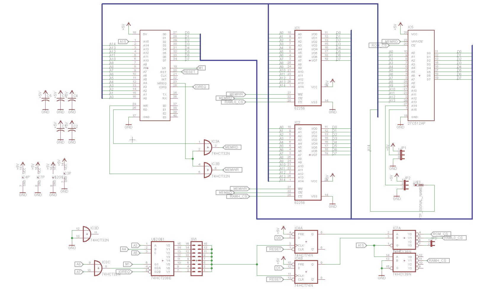
The basis for this came from Grant Searle’s CPM project, though I have made a few modifications. I wanted it to be easily possible to switch back to ROM under program control, and to bank switch in additional RAM chips if we wanted to. Here is my schematic:

RC2014 banked ram/rom board, schematic

There are a total of two RAM chips, IC1 and IC2. IC2 is always active and is addressed from 8000h to FFFFh. IC1 is only active after it has been bank switched in and is active from 0000h to 7FFFh. We could have lowered the chip count by using a single 64KB RAM chip and playing a few different tricks with the addressing, but I already had 62256 32KB RAM chips, and decided to optimize keeping my inventory simple.

IC5 is a 64KB EPROM. It’s also addressed a 0000h. There are some jumpers to the A14 and A15 pins of the EPROM that allow us to map in a 16KB chunk out of the 64KB EPROM. This allows us an easy way for us to store four different programs in the ROM and select which one by moving jumpers about. Spencer did the same thing with the RC2014’s 64 KB ROM board.

So the trick, and the purpose of the other four ICs, is to be able to selectively switch between the EPROM, IC5, and the low RAM chip, IC1. We start with a 74HCT238E 3-to-8 decoder (NOTE: a 74HCT138 might also work and simplify inventory requirements; need to try this). This sets a port that can be used to control the bank switching. The addressing is a little bit different that my other 74HCT138-based boards in that I spaced the addressing ranges 8h apart. You can put the bank-select port at 0h, 8h, 10h, 18h, 20h, 28h, 30h, or 38h. I did this to maintain compatibility with Grant Searle’s CP/M design, which places the bank switch address at 38h.

Writing to the bank select port clocks D0 and D1 into a pair of flipflops on a 74HC84N. The RC2014’s RESET pin is connected to the clear pin of the flipflops, so that a reset will always reset the flipflops back to zero. This allows us to write any of four values — 0, 1, 2, or 3 — to the flipflops and will serve as our bank select. The default is zero.

The output of these flipflops is used as the input to a 74HCT139N dual 2-to-4 decoder. When A15 is high, it will cause the 74HCT139 to assert low one of four outputs based on the value it’s currently receiving from the flipflops. Output 0 is connected to the ROM. Output 1 is connected to the RAM. Outputs 2 and 3 are connected to a header to allow additional RAM chips to be added at a later date.

The second half of the 74HCT139N is wired up to function as an inverter. I needed an inverter to invert A15 so that it could drive the IC2 from 8000h to FFFFFh. Rather than add a 7404 of inverter for this purpose, I figured out how to repurpose the unused half of the 74HC139.

To make a long story short:

  • On reset, the EPROM (IC5) is selected
  • If you write a 0 to the bank select port, the EPROM (IC5) is selected
  • If you write a 1 to the bank select port, the LOW RAM (IC1) is selected
  • If you write a 2 to the bank select port, pin 1 of JP3 is selected, to support an external RAM chip
  • If you write a 3 to the bank select port, pin 2 of JP3 is selected, to support an external RAM chip

Here’s how the CP/M boot sequence works:

  1. The ROM loads the CP/M runtime and BIOS into RAM at D000h and E600h respectively. The entrypoint to start CP/M is at FFFEh.
  2. The ROM then jumps to RAM at address FFFEh
  3. The CPM bios writes 1 to port 38h. This causes the ROM to be deselected and the low RAM to be selected in it’s place. This selection remains in effect until the board is reset (or some program writes a different value to port 38h).
  4. We’re now running entirely in 64KB RAM. The ROM is completely out of the picture.

Hardware implementation

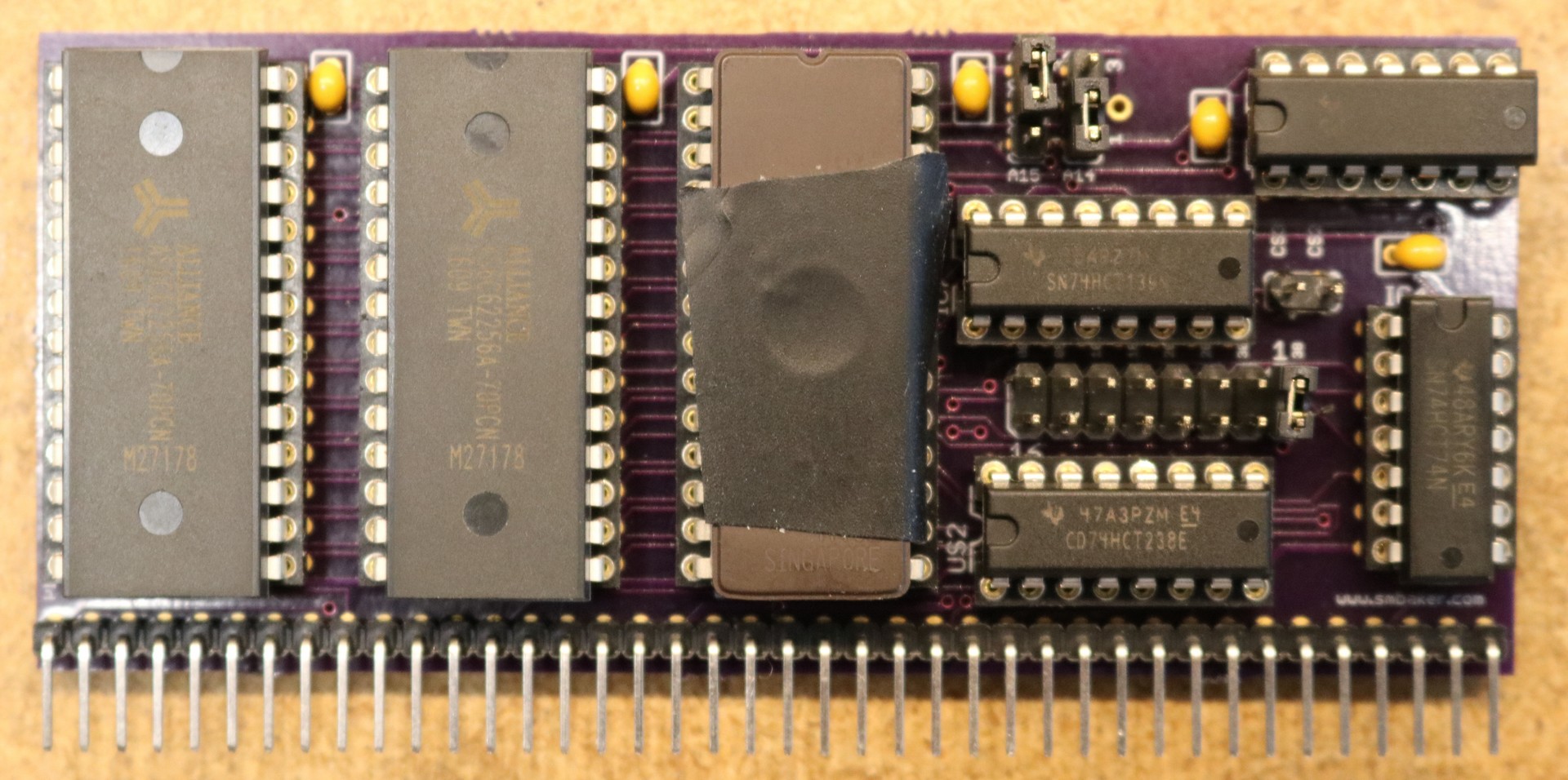
Here is a picture of the completed RAM/ROM board

RC2014 Banked RAM/ROM board

For the other necessary boards (SIO, CompactFlash), see my other blog posts.

Modifications to CP/M

I made a few modifications to Grant Searle’s CP/M monitor, BIOS, and other support tools.

  • I put the compactlflash at port E0h instead of at port 10h. I like keeping the 00h-79h range free for peripherals like IO boards and such.
  • I put the SIO/2 at port 80h instead of port 0h. This is for the same reason as above.
  • I significantly increased the size of the serial receive buffer. Flow control isn’t working for me, and XMODEM transfers were overflowing the buffer at its original size.
  • Optionally, I have support for my CTC board at 90h. This is a work in progress and it to allow baud rates other than 115,200.
  • I modified the bootstrap procedure that loads download.com and the format tool to load from 8100h instead of 4100h.

Installing CP/M on the RC2014

I followed the instructions on Grant Searle’s page, and things went amazingly well and trouble free

  1. Hardware Configuration for RC2014
    1. SIO/2, CompactFlash, and Banked RAM/ROM board installed
    2. Monitor ROM installed
  2. Format the Flash Card
    1. Boot to monitor
    2. paste form64.hex into monitor
    3. type “G8100″
    4. (note: assumes smbaker’s changes that relocate from64 from 4100h to 8100h)
  3. Install CP/M
    1. Boot to monitor
    2. paste cpm22.hex
    3. paste cbios64.hex
    4. paste putsys.hex
    5. type “G8100″
    6. (note: assumes smbaker’s changes that relocate putsys from 4100h to 8100h)
  4. Boot into CP/M the very first time
    1. Boot into monitor
    2. Press “X” (boot to CPM)
    3. Press “Y” (confirm boot)
    4. You’re now staring at the A> prompt
  5. Install Download.com
    1. Press RC2014 reboot button while CPM is running. This will boot to the monitor.
    2. Paste down8100.hex
    3. (note: assumes smbaker’s change that relocates download.hex from 4100h to 8100h)
    4. Type “GFFE8″. This will cause the monitor ROM to bank switch, and automatically copy down8100.hex from 8100h to 100h
    5. You should be starting at the A> prompt again
    6. Type “SAVE 2 DOWNLOAD.COM”
    7. This will cause the program that is currently located at 100h to be saved to disk under the name “DOWNLOAD.COM”

At this point, you have a minimally functional CP/M system, with a single program called DOWNLOAD.COM that you can use to download other programs into the RC2014. Grant Searle’s page has links to a bundle of useful tools (LOAD, SUBMIT, DISPLAY, PIP, STAT, DDT, DUMP, ED, ASM). I recommend installing all of these, as they are pretty useful.

I also found it very handy to install XMODEM, since my terminal program has a built-in XMODEM client. I found some XMODEM source in a google thread at https://groups.google.com/forum/#!topic/comp.os.cpm/-oI2ydzFrC8. There were a few issues I had to fix in this XMODEM program to get it to work on my CP/M RC2014. These are documented in patches/xmodem.patch in my RC2014 github repo. The two primary issues I ran into were a stack overrun which forced me to relocate where xmodem was storing its stack, and a call to RXTIMR that was causing the receive routine to prematurely terminate.

Once XMODEM is installed, it’s a simple matter to upload additional software like this:

  1. type this: “xmodem filename.ext /r /x0″
  2. initiate an xmodem upload in your terminal

The /R instructs xmodem to operate in receive mode. The /X0 tells it to transfer using the CP/M console.

CP/M Software Resources

There are several sites with useful resources on the web. At RetroArchive you can find Zork 1-3, a variety of programming languages including Microsoft Basic, etc. Note that some of this appears to be commercial software (for example, Turbo Pascal) so I haven’t provided direct links here. Note that there is both -86 software and -80 software on this site. For a Z80, you’ll want the -80 software.

cpm.z80.de is another resource, and has programming languages, tools, emulators, etc. There seems to be a lot more -86 software here than -80 software though.

RAM/ROM PCBoard Ordering

As usual there’s an Osh Park link for ordering the banked RAM/ROM board:

Order from OSH Park

As with all the other boards, I don’t make any money from this. I’ve just made the boards available on Osh Park for anyone else who wants them.

To order the other boards (SIO, CompactFlash), see my other blog posts.


Z80 Power-on reset circuits

$
0
0

If you’ve watched my recent video on the Nixie tube clock, you may have noticed that my clock didn’t have a power-on reset capability. It sat there locked up until someone flipped the reset switch.

I spent some time looking over the Internet and came up with two options for reset circuits:

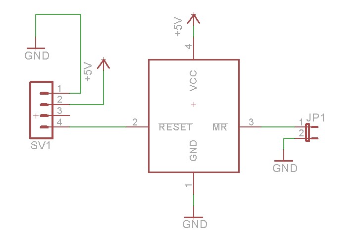
Option 1: The MAX811

Max811 Reset Circuit

The MAX811 is what Maxim refers to as a microprocessor supervisory circuit. They watch the vCC signal and when it falls below a preset threshold, they will assert the reset signal for 140 milliseconds. You can buy the MAX811 in a variety of different thresholds. The ones I chose were the MAX811LEUS, which has a threshold of 4.63V, which seems appropriate for a 5V project like my RC2014. Since the MAX811 is designed to serve exactly this one purpose of voltage monitoring and asserting a reset, it does it quite well.

The !MR signal is for connection to an external reset button.

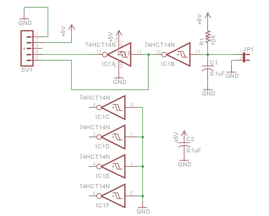
Option 2: An RC timer reset circuit

RC Timer Reset Circuit

The RC Timer reset circuit uses a resistor and a capacitor to cause the reset signal to be asserted when power is applied. When power is disconnected, C1 will approach ground. As power is supplied, C1 will charge via R1. If the voltage on C1 is below the threshold necessary to be detected as a logical high by IC1B, then IC1B will output a high, which in turn causes IC1A to output a low. This asserts our reset.

As C1 charges, it will eventually be above the threshold necessary to be detected as a logical high. IC1B will output a low, and IC1A will invert that to a high. This drops our reset signal and allows the microprocessor to run.

Although I used a schmitt trigger inverter in this schematic, it should be possible to use a regular inverter, which the caveat that the reset signal might flop on and off wildly as C1 is charging (schmitt trigger has hysteresis which should prevent this from happening).

Note that the above schematic has both an R and a !R output, this is handy if you have circuits that are both reset low (like a Z80) and reset high.

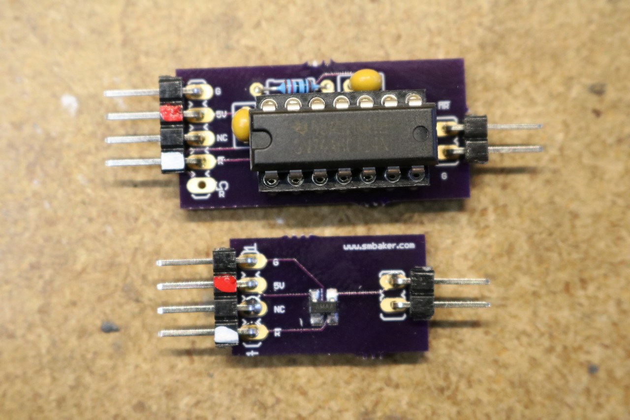
Implementation

I constructed both of these circuits and they are shown below:

Reset Circuits, Prototype

I tried out both of them in my RC2014 Nixie Tube Clock, and they both worked fine for power-on reset. I ended up going with the RC schmitt trigger version as it seemed more accurate to the period.

PC-Board availability

Circuit boards for both of the above are available on Osh Park:

Max-811 version:

Order from OSH Park

RC-Timer version:

Order from OSH Park

Z80 Retrocomputing 12 – Talking Nixie Tube Clock

$
0
0

In this post, I assemble a bunch of RC2014 boards and make a talking Nixie Tube Clock

This project Makes use of the following RC2014 boards:

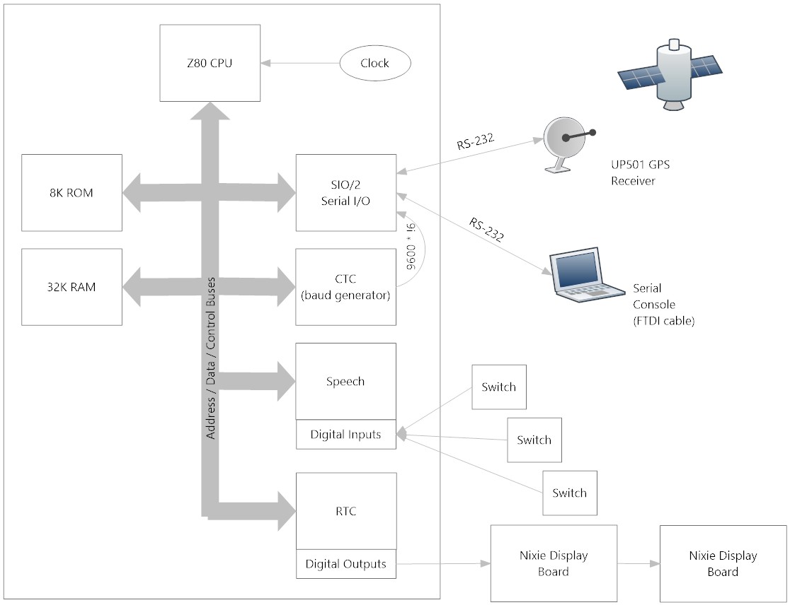
Here’s a diagram of how the boards all work together:

Talking Nixie Tube Clock, Diagram

I chose to use a UP501 GPS module so that the clock can set itself from GPS, rather than requiring me to manually set the time. That’s the one part of the clock that doesn’t fit the “retro” theme, since it is a modern GPS module. Alternatively, the clock can be operated from a BQ4845 real-time clock chip, which would be more fitting with the retro theme.

The SIO/2 board provides the TTL-level serial port that talks to the GPS, as well as a port for console. There’s no real need for a console, other than debugging. Since the GPS module operates at 2400 baud, I needed a baud rate generator, and that’s the purpose of the CTC board.

Speech synthesis is provided by an SP0256A-AL2 speech synthesizer chip. The speech synthesizer board also includes a general-purpose input port, which I use to implement the front panel buttons. One momentary switch is used to announce the current time.

We also need RAM and ROM. I ran out of backplane slots, so I used my dual RAM/ROM board.

Here are a couple high-resolution pictures of the completed clock:

RC2014 Talking Nixie Tube Clock, Front View

RC2014 Talking Nixie Tube Clock, Top View

The software is written entirely in assembly, and is available in my github repo at https://github.com/sbelectronics/rc2014.

Z80 Retrocomputing 13 – RC2014 VFD Display Board

$
0
0

In this post, I interface a vacuum fluorescent display to the RC2014:

Sourcing displays

These vacuum fluorescent display modules can be found easily on ebay, just search for “Noritake VFD”. They’re available in a variety of different configurations from single line displays to four line displays. A word of caution about the larger displays — some of them, such as 4×40, do not offer the “8080 mode” that I used in this blog post and will require different interfacing techniques.

The VFD modules will typically include a jumper on the back that selected between “68″ mode and “80″ mode. For the purposes of this blog post, we want to operate in 80 mode. Every one of these modules I’ve seen has had this jumper unbridged, so you’ll need to bridge it, either by soldering across the jumper or by installing a two pin header and a shunting block.

VFD Board Design

Here’s a schematic of the VFD display board:

RC2014 VFD Board, Schematic

You’ll notice that there are two VFD modules shown in the schematic. One is a 1×14 SIP header footprint, and the other is a 2×7 SIP header footprint. The Noritake modules you find on eBay will typically be one of the other.

I included a potentiometer for contrast control. This isn’t used for VFD displays, but may be useful for LCD displays (many LCD displays use the same pinout as these Noritake modules).

We have the same 74HCT138N decoder logic that I used for most of my other RC2014 compatible peripheral boards. There’s also a 74HCT32N OR gate, that’s used to combine the RD signal with the CS signal, and the WR signal with the CS signal to generate IORD and IOWR signals. That’s what the Noritake module will expect when operating in 8080 mode.

VFD Board Implementation

Here’s the completed board:

RC2014 VFD Board, Completed

Bill of materials

  • PCB, Osh-Park
  • 1×14 or 2×7 female 0.100″ header
  • 2×8 male 0.100″ header
  • 74HCT138N
  • 74HCT32N
  • 0.1uF capacitor
  • 40-pin right angle SIP header
  • IC sockets as desired

PC-Board Ordering

As usual, I’ve made the board available on Osh Park:

Order from OSH Park

Z80 Retrocomputing Part 14 – RC2014 Floppy Controller Boards

$
0
0

In this post, I build a couple of different floppy controllers for the RC2014, and run CP/M on them.

If you haven’t read my other video on CP/M on the RC2014, please start there.

Motivation

Why a floppy controller when I have a perfectly good CompactFlash board? The floppy is more period accurate. If you’re building a retrocomputer, then speed and storage density are probably not your primary concern (just go buy yourself a raspberry pi instead!). The goal with retrocomputing is trying to reproduce the technology of a bygone era. For most of us that is probably the floppy disk.

There’s a number of possible floppy drives that can be considered, most notably the 8″, 5.25″, and 3.5″. Of these, the easiest to obtain drives and media for is the 3.5″. You might even have a drive laying around from a defunct computer. So let’s start with the 3.5″.

Design

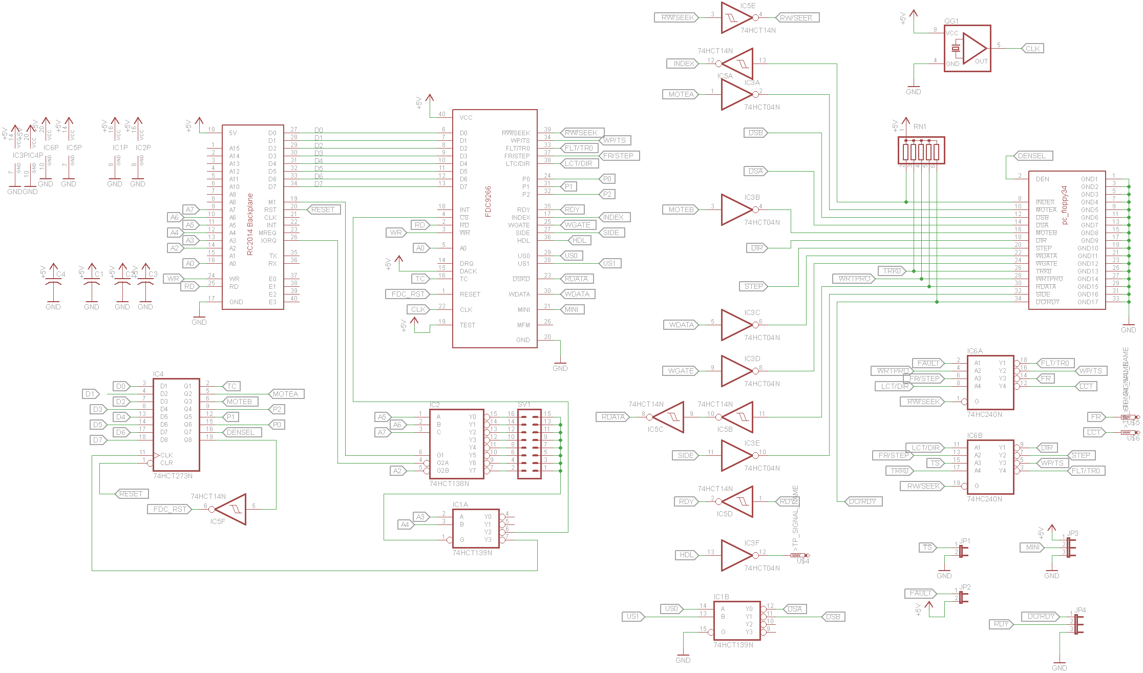
I started by looking on the Internet with a google search for “Z80 Floppy Controller”. The first result, which seemed very promising was the N8VEM DiskIo V3 board, which used the FDC9266 Floppy Controller. I adapted this circuit for the RC2014:

RC2014 Floppy Controller, FDC9266 Version

This design is based almost entirely on the DiskIO V3.

As you can see, the FDC9266 implementation is fairly complex. The guts of the circuit is the FDC9266 itself. The complication is that it uses active-high signals whereas our 3.5″ PC floppy drive uses active-low signals. This leads to a whole lot of hex inverters, on nearly every signal that goes between the controller and the drive. For outputs, we us a 74HCT04. For inputs we use a 74HCT14, which offers a schmitt trigger input. Note also the pullups on the lines from the floppy.

An additional complication is that five of the output pins of the FDC9266 (WP/TS, FLT/TR0, FR/STEP, LCT/DIR) are multiplexed. They have one meaning when seeking and a different meaning when reading/writing. This leads to a 74HCT240 being used to demultiplex these signals. The FDC9266 doesn’t give us control of the motors, and it needs some additional control signals (P0, P1, P2, TC). This leads us to implement a latch using a 74HCT273N. Finally, the FDC9266 outputs its drive selects not as individual control likes but rather as a 2-bit binary value, leading to the need for a 74HCT139 to convert those two bits into a set of drive selects.

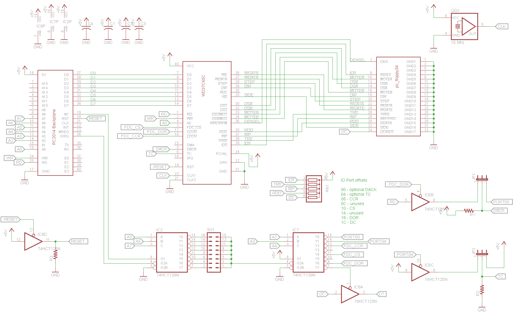
No sooner did I order the above design from Osh Park did I then stumble on a simpler design using the WDC37C65:

RC2014 Floppy Controller, WD37C65 version

This design, based on the Zeta 2 Single Board Computer by Sergey Kiselev, fixes several of the gripes about the FDC9266. It outputs active-low signals so the plethora of inverters are not needed. It does not multiple pins, so the demultiplex chip is not needed, it has a built in DOR register so there’s no need for an external latch, and it outputs drive selects directly so we need no 74HCT139. The result is that many chips are eliminated.

I built and tried out both these designs, and I vastly prefer the WD37C65 due to the reduced complexity.

Implementation

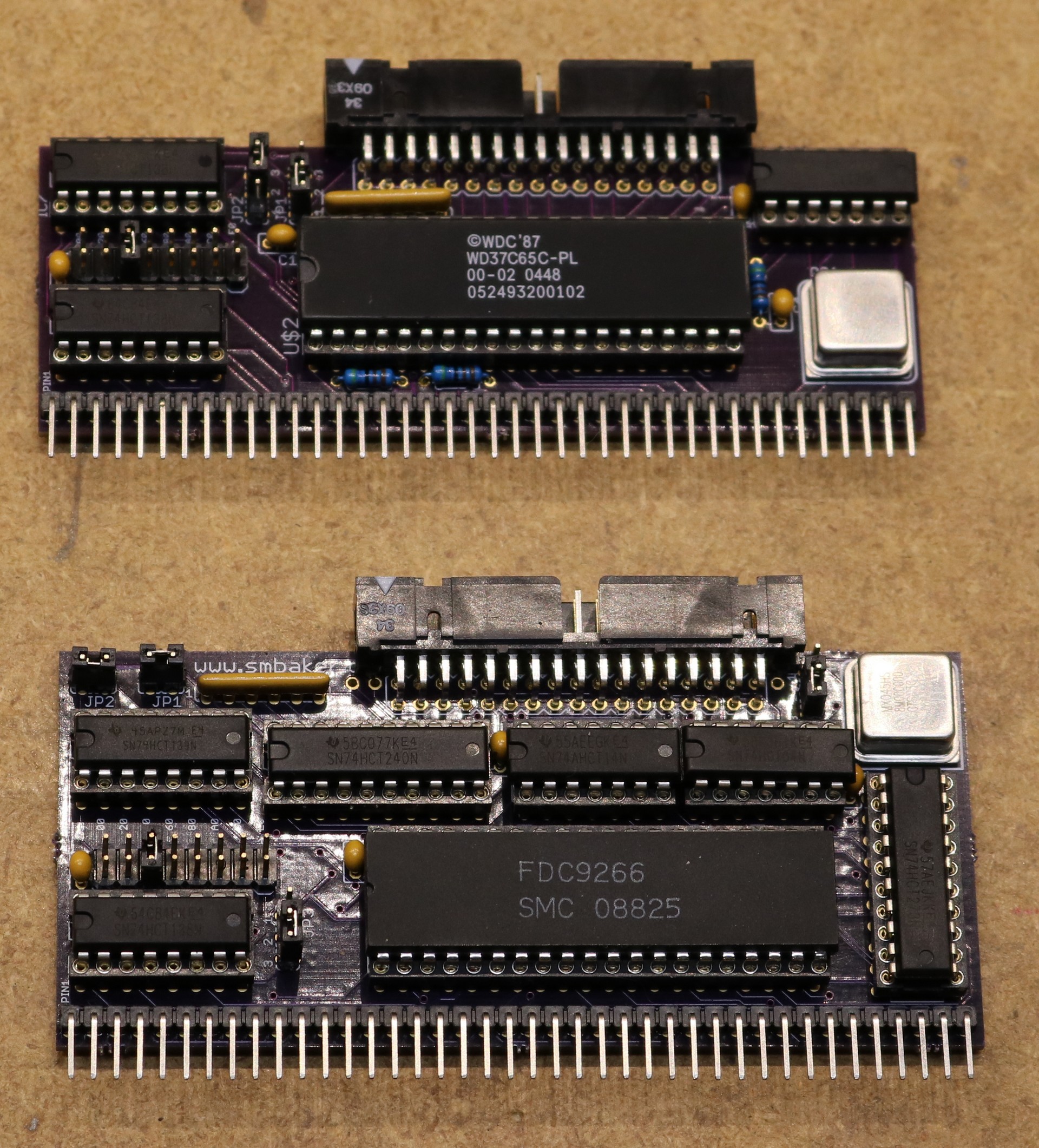
I ordered both boards from Osh Park and built them up:

RC2014 Floppy Controller Boards (WD37C65 Top, FDC9266 Bottom)

The reduced complexity of the WD37C65 circuit is evident from the lower chip count. It’s not earth shattering, but any simplification is a benefit. In addition, having the DOR register built into the chip seems to make the programming easier.

Software

To make this thing work, I used the floppy driver from RomWBW. I modified the Grant Searle CP/M monitor, BIOS, and other assorted tools to use this driver, since Grant Searle’s CPM distribution has closer compatibility to the RC2014 I’ve built than RomWBW does. In the future, I’m probably going to transition my RC2014 over to RomWBW (future blog post!), but that’s going to take a bit of work.

I’ve committed the changes to the RomWBW driver to my github repo. There’s probably a few bits and pieces that I need to get together for anyone who wants to reproduce this — let me know what is missing if you try to build one of these yourself for the RC2104.

Using 8″ or 5.25″ floppy drives

I’ve managed to find myself an 8″ floppy drive on eBay and I’m going to give that a shot in a future blog post. There’s a little bit of complication due to a few extra pins (RWC = Reduced Write Current, and HDL = Head Load). Both chips have support for these pins, although in my WD37C65 board I failed to break the pin out to a pad (Bad! Always break unused pins out to a pad, as you never know when you’re going to use them!).

Using a 5.25″ drive will probably not be all that difficult, since we don’t have to worry about additional signals. It’ll just take some modifications to the CP/M bios to tell it what kind of drive (tracks, sectors, etc) to expect.

Board Ordering

As always, I’ve enabled the boards to be shared on Osh Park:

FDC9266 board:
Order from OSH Park

WD37C65 board:
Order from OSH Park

Building a Zeta V2 Single Board Computer

$
0
0

I was so impressed with the Zeta 2 design when I built my floppy controller for the RC2014 that I decided to go ahead and build a Zeta V2 as well!

As you’re probably aware if you’ve read my previous blog posts, one of my recent hobbies has been retrocomputing, building computers based on the techniques of the 1970s and 1980s. Most of the projects I’ve built have been based on the RC2014, but I came across the Zeta 2 and decided to give it a go as well. The Zeta 2 is designed by Sergey Kiselev. There are PC-Boards available at the Vintage Computer Forum for $20 each.

The Zeta 2 differs from the RC2014 in that the Zeta 2 pretty much gives you everything you’re going to need (CPU, Parallel IO, Serial IO, Storage, Ram, ROM, clock, etc) all in a single PC-Board. As such, it’s relatively easy to assemble a fully-functional CP/M computer and has a working CP/M distribution that runs right out of Flash ROM. If you want to get a fully functional CP/M computer up and running quickly, the Zeta 2 is a great way to go.

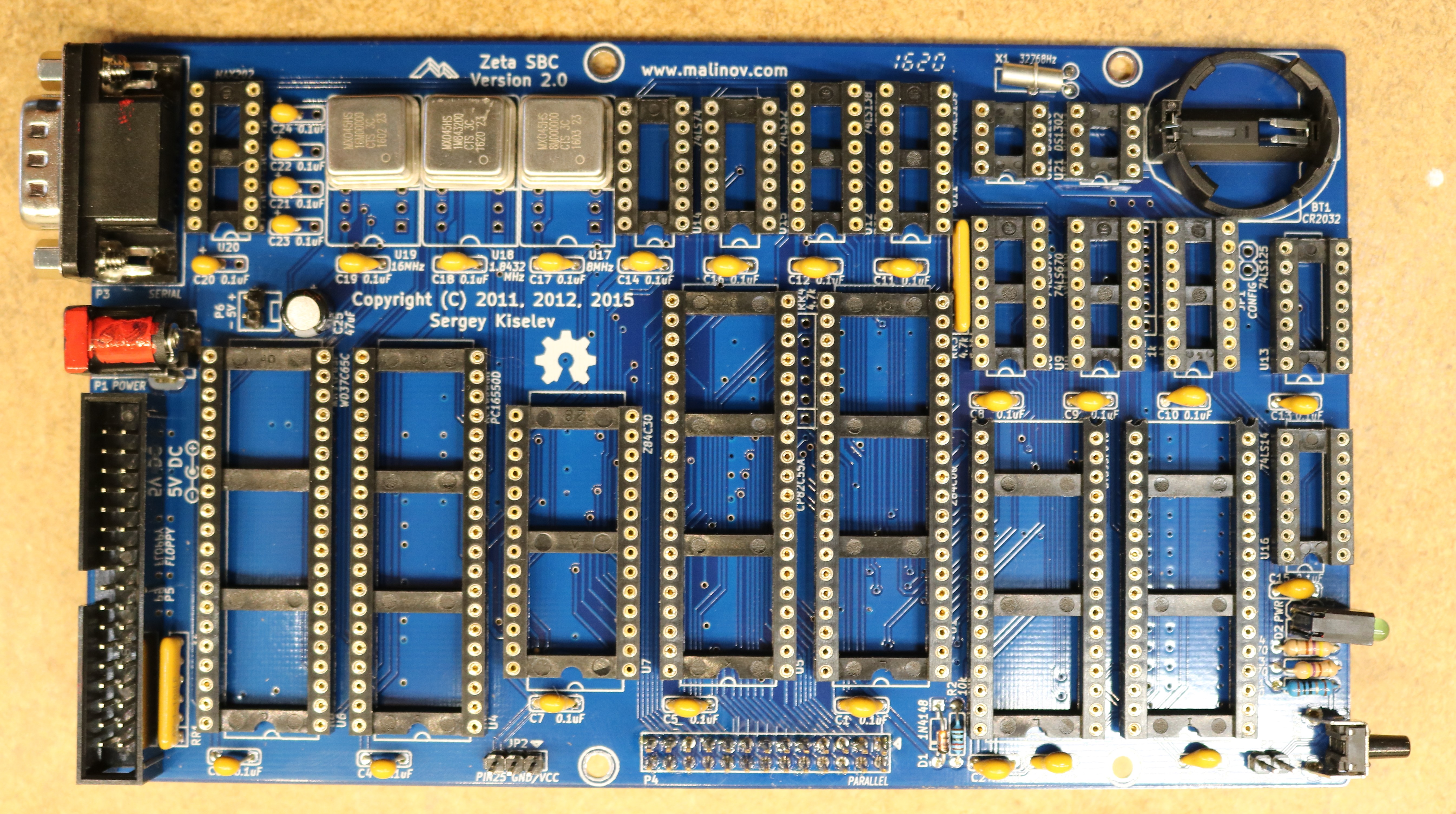
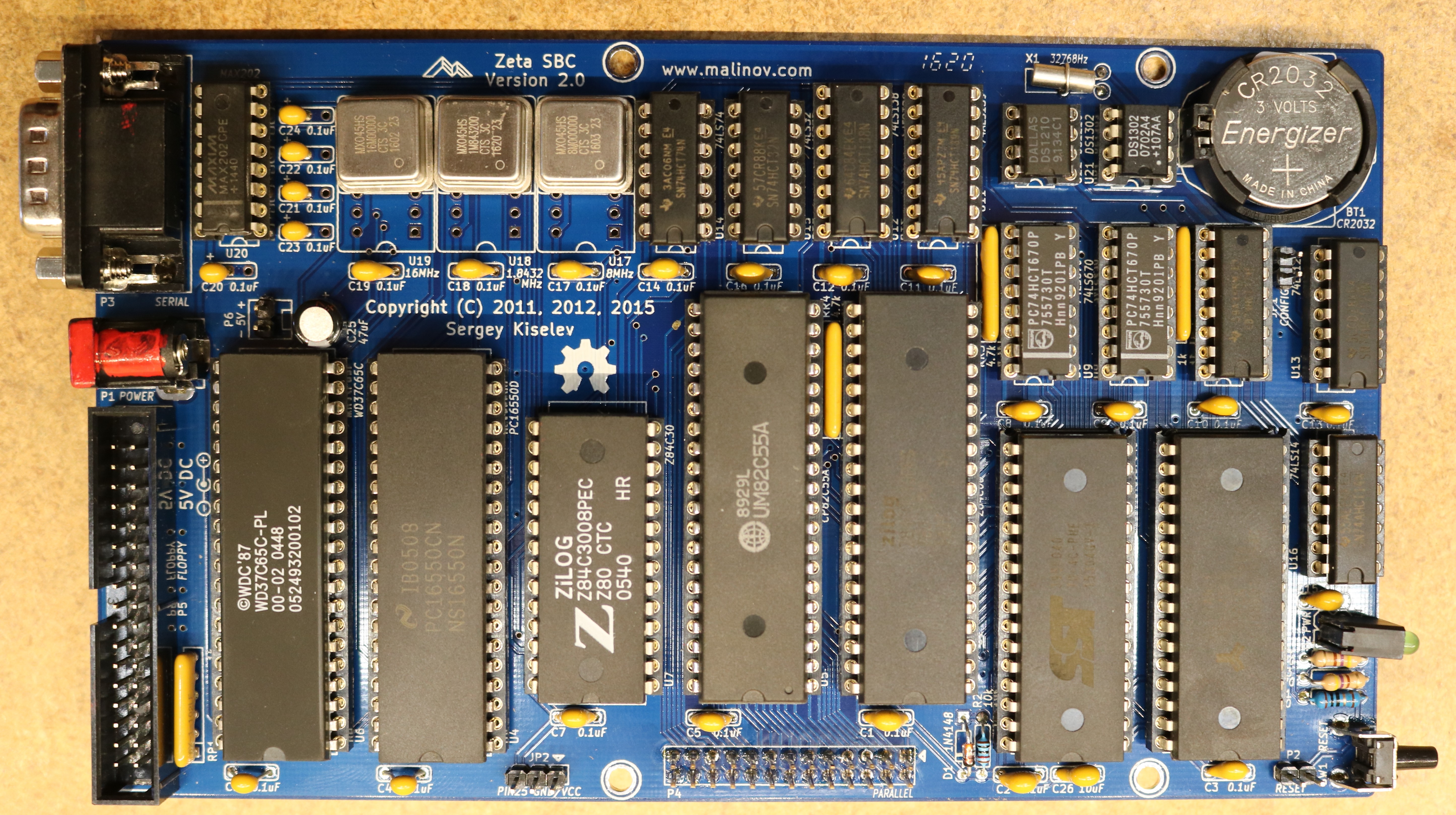
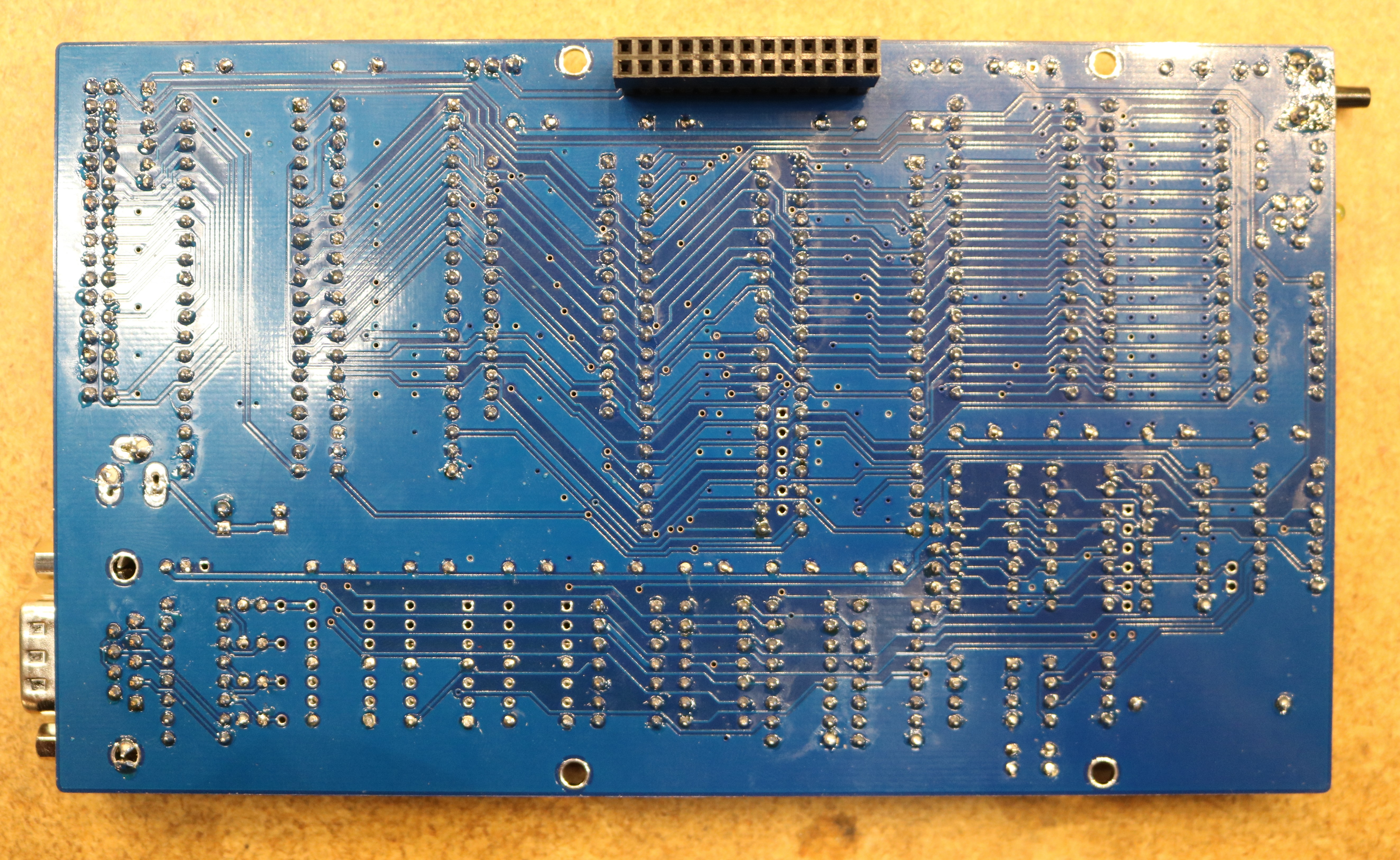
Here are a couple pictures of my Zeta 2 Build:

Zeta2, Just the Sockets Installed

Zeta 2, Complete

zeta 2, bottom

A few of the features of the Zeta 2:

  • 512K Flash Memory, allows CP/M to be booted from Flash, and mounts Flash as a CP/M disk including many tools (assembler, editor, …)
  • 512K Flash ROM, can be used as RAM Disk. Supports battery backup.
  • 16550 UART provides a single serial port
  • 8255 PIO supports up to three 8-bit serial ports
  • Dallas 1210 Real-Time Clock
  • WD37C65 floppy controller, easily supports 3.5″ PC Floppy Drives

Most of the ICs are easily sourced from places like Digikey or Jameco. A few of the more unusual ones, like the WD37C65 floppy controller, you may have to find at a site like eBay. Make sure to plan out your part acquisition accordingly (if you order some chips from eBay, note that suppliers are often in China and it may take a few weeks for parts to arrive).

As you can see in the bottom view of the board, I used a stacking header. This allows the parallel port to be connected from either the top or the bottom. The reason for this is that there’s a companion board designed to work with the Zeta 2 called the ParPortProp:

Zeta 2, ParPortProp companion board

The ParPortProp uses up the A and C ports of the Zeta 2’s 8255 PIO chip (leaving only 8 bits of PIO remaining), but provides you with:

  • VGA Monitor Output
  • PS/2 Keyboard Input
  • SD-Card socket (mounted in CP/M as several 8 GB drives)
  • Speaker
  • Another serial port

The ParPortProp uses the Parallax Propeller micocontroller, a relative modern chip, so it diverges a bit from what we might consider classic retrocomputing. The Zeta 2 is still your “computer”, but the ParPortProp is acting as a terminal attached to the computer. This lets you connect a keyboard and monitor up to your Zeta 2, giving you a standalone computer than you can directly interact with.

The biggest disadvantage of the ParPortProp is the amount of PIO that it consumes. If you’re like me, and you like interfacing lots of things to your projects, then you might find the remaining 8-bits of PIO somewhat unsatisfying. The ParPortProp is completely optional though.

Conclusion

I really enjoyed building this kit. I was able to get CP/M up and running almost trivially. CP/M runs out of ROM so even if you don’t have a storage subsystem handy (floppies, SD Card, etc), you still have a fully functional computer.

Qume 842 8″ floppy drive with a RC2014 Z80 retrocomputer

$
0
0

In this video, I try out a pair of Qume 8″ floppy disk drives with the RC2014:

Most people who have read my retrocomputing series probably have some familiarity with 3 1/2″ drives or with 5 1/4″ drives. The 8″ drive preceded the 5 1/4″. I never had the experience, having entered the computer scene in the early 80s with a TRS-80 coco, starting out with a cassette tape and then moving to a 5 1/4″ drive. As such, I was anxious to try out some 8″ drives.

Selecting a drive

I started out by watching eBay for a couple of weeks. There are several different models of 8″ drive that show up — Shugart and NEC seem to be the most popular, but you’ll also see Qume, Tandon, and some rarer drives. There’s several different parameters to look for in drives:

  • Hard Sectored or Soft Sectored. Hard sectored drives feature physical marks on the drive surface that denote sector boundaries. These are typically picked up by something like an optical sensor. Soft sectoring uses index marks recorded on the drive. You record these marks during the formatting process. Soft sectoring seems to be the more modern of the two technologies.
  • Single Sided or Double Sided. Some drives have two heads, and some have only one head.
  • Single Density or Double Density. Some drives support a data rate of 250 Kbps using FM, whereas other drives support a data rate of 500 Kbps using MFM.

I knew early on in my selection process that I wanted a soft sectored double-sided double-density drive.

Also note that a variety of power sources are required for the typical 8″ floppy. Early drives required line power (120 VAC or 240 VAC) for the spindle motor. If you get one that requires line power, make sure it’s compatible with your country. Also required is typically 24 VDC and 5 VDC. Occasionally -5 VDC is also required. You may have to build yourself a custom power supply to get your ancient 8″ floppy drive working.

When evaluating drives on eBay, you have to be wary that whatever you purchase may not function. 8″ drives could easily be nearly 50 years old. They may suffer from controller failures, head failures, alignment issues, etc. Often the parts to repair them are no longer manufactured. Some contacts on the vintage computer forum warned me about buying drives from eBay sources without a guarantee, that I could easily be buying junk that was not financially feasible to repair.

Nevertheless, when a pair of Qume drives plus a case showed up for around a hundred bucks, I decided to give them a shot.

Building a 34-50 adapter

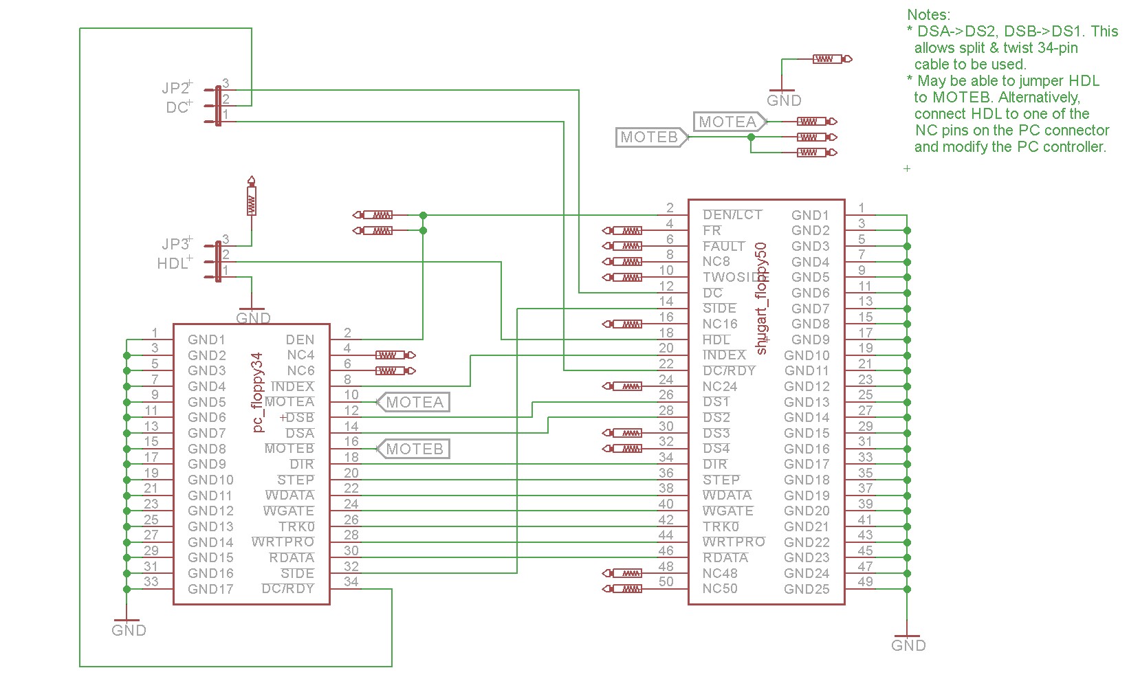
The controllers that I implemented for the RC2014 used 34 pin connectors. The typical 8″ drive uses a 50 pin connector. Thus, I had to implement a 34-to-50 adapter. You could do this by hacking a ribbon cable, but it was easier for me to design a PCB with a couple of headers. Here is my schematic:

Floppy 34-to-50 pin adapter schematic

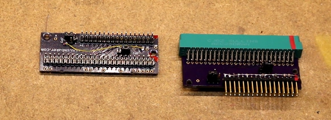
and the boards I implemented:

Floppy 34-50 adapters, built

The board on the left used pin headers. The board on the right used a card-edge connector for attaching to the 8″ so I can plug it directly into the 8″ drive. The card edge connector presented some particular challenges (hence it’s upside-down) and you can hear about them in the video.

Most of the signals are a straightforward mapping from the 34-pin connector to the 50 pin connector, but there are a few exceptions:

signal 34 pin pc connector 50-pin shugart connector
Density Select 2
Reduced Write Current ** see notes ** 2
Head Load ** see notes ** 18
Index 8 20
Second Motor 10 (MOTEA)
First Drive Select* 12 (DS B) 26 (DS1)
Second Drive Select* 14 (DS A) 28 (DS2)
First Motor 16 (MOTEB)
DIR 18 34
STEP 20 36
WDATA 22 38
WGATE 24 40
TRK0 26 42
WRTPRO 28 44
RDATA 30 46
SIDE 32 14
DC/RDY 34 12

Notes:

  • The odd pins (1,3,5,7,9,..) are all grounds.
  • I described DSB and MOTEB as the PC’s “first drive select” and “first motor”. This is because PC floppy cables typically have a split and a twist, that reverses the DSA/DSB and MOTEA/MOTEB.
  • 5.25″ and 3.5″ floppy drives often have motor signals to turn the spindle on and off. 8″ drives often do not. For example, my Qume runs the motor all the time.

There’s two particularly problematic signals that we have to deal with for the 8″ drive:

  • Reduced Write Current (RWC), also sometimes called LCT. As the head moves from the outside of the disk to the inside of the disk, the circumference of the tracks decreases. For this reason, the typical 8″ floppy drive will reduce the current to the write head on these inner tracks. In theory the WD37C65 controller I chose should support this signal (it repurposes the DEN pin), but I was unable to get it working. In my build, I have restricted the tracks to those that don’t require reduced write current until I get this resolved.
  • Head Load (HDL). This signal tells the 8″ drive to activate a solenoid that will load the head against the disk surface. Many people recommend tying the PC’s MOTEB signal, since the behavior is similar. This means when the controller tells the drive to turn its spindle motor on, it will cause the head to be loaded.

With either of these two signals, you might not even need them. You’ll have to consult your 8″ drive’s manual. My Qume drives do need RWC, but they can be jumpered to operate HDL from drive select if desired.

The controller I’m using, the WD37C65, does support a native head load signal. I routed the 8″ HDL (pin 18) to one of the PC connector’s unused pins (6), and then wired my controller to supply head load on pin 6.

Building a power supply

My two Qume drives required +24VDC and +5VDC, as well as line voltage. Fortunately, no negative voltages were required. I constructed a power supply mostly from parts from Jameco electronics:

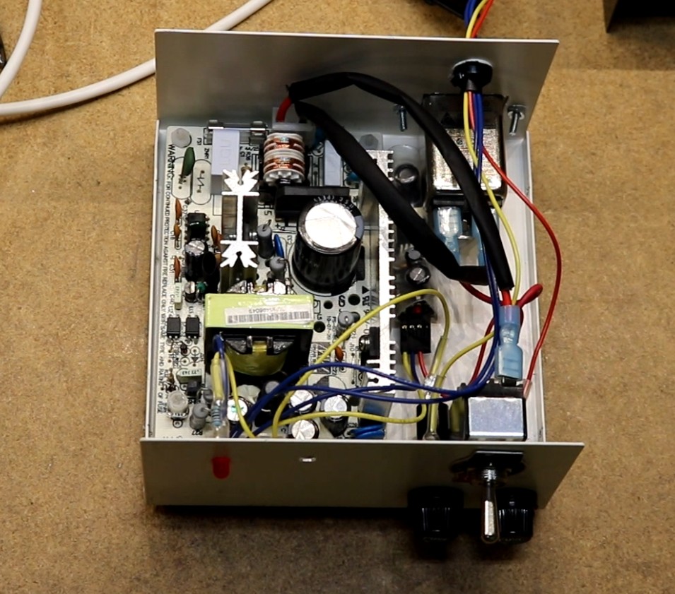
+24V / +5v power supply

The large open-frame power supply is a 24V supply from Jameco electronics. I also added a power entry filter that accepts standard AC power cables, a toggle switch, a couple of fuses, and a status LED.

It’s hard to see, but tucked alongside the open-frame 24V supply is one of my LM2576 5V switching modules. This supplies the 5V power necessary for the drive.

Modifying RomWBW

The CP/M distribution I’m currently using on the RC2014 is called RomWBW. It already has a profile for supporting double-sided/double-density 8″ drives, so little work was necessary. All I did was change the number of tracks from 77 to 40 to workaround my current RWC limitation.

Z80 Retrocomputing 15 – CP/M on RC2014 Revisted, Using RomWBW

$
0
0

In this video, I build a new Flash ROM / RAM board and use it to install the RomWBW CP/M distribution on the RC2014:

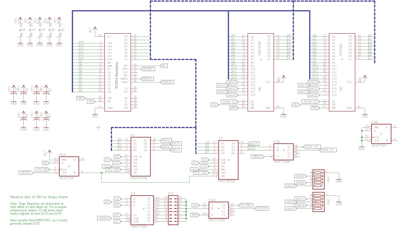
I’ve already done one video on CP/M on the RC2014, but when I built the Zeta 2 Single Board Computer, I liked Sergey Kiselev’s design so much that I thought I’d try to adapt it over to the RC2014.

Overview of the new design

The new design, based on the Zeta 2 by Serget Kislev, uses a 512 KB Flash ROM and a 512 KB static RAM. There are two register file chips that implement a 7-bit paging register. This allows you to slice up the Z80’s 64 KB address space into four windows, each of which can point to any 16 KB page in ROM or RAM.

There are several advantages to the new design:

  • The CP/M operating system and BIOS is built into ROM
  • ROM disk allows over a dozen CP/M applications and tools
  • RAM disk allows programs to be downloaded, assembled, etc.
  • No external storage (CompactFlash or Floppy) is needed for a basic CP/M system
  • Flash ROM can be reprogrammed without needing to be erased

Schematic

Here’s a picture of the schematic

RC2014 Flash ROM / RAM Schematic

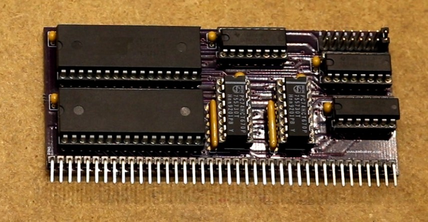
Implementation

Here’s the board I built

rc2014 Flash ROM and RAM board

Modifying RomWBW

The CP/M distribution that runs on the Zeta 2 is called RomWBW by Wayne Warthen. Since the RC2014 is not exactly a Zeta2, I had to make a few modifications:

  • Added support for the Z80 SIO/2 chip
  • Added support for the ICAI chip (for those using the original RC2014 serial board)

Github makes it very easy to fork an existing project and make available your own changes. My fork of RomWBW is located at https://github.com/sbelectronics/RomWBW

Board Ordering

As usual, the boards are up on osh park:

Order from OSH Park


Z80 Retrocomputing 16 – Unix on RC2014

$
0
0

I this video, I install a Unix variant called Fuzix on the RC2014:

No new hardware is introduced in this video, I use the same Flash-ROM/RAM board that I used for RomWBW. Thanks to William Sowerbutts for pointing me to the distribution and helping me along with a few issues.

There were a couple of changes necessary to get FUZIX to work on my RC2014. Most significantly, I added support for the SIO/2 and ACIA. I also removed support for the real time clock and faked it out to always return a time of zero. You can find my changes in my fork of fuzix at https://github.com/sbelectronics/FUZIX.

Building an Xi 8088 PC

$
0
0

In this video, I construct an Xi 8088 PC, based on the design by Sergey Kiselev:

Overview

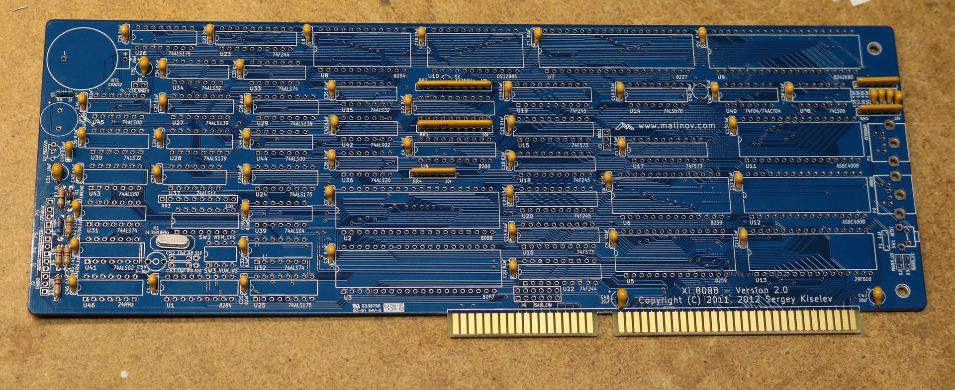
This was a long, involved project. I started out by ordering a set of boards from Todd over at the retrobrew forums:

A set of Xi 8088 and related PC boards

These boards included:

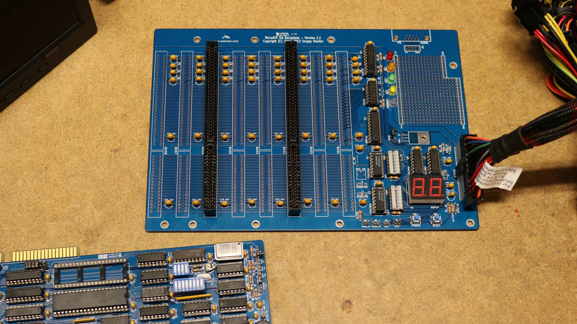
  • 8-slot backplane with BIOS POST code display
  • Xi 8088 CPU board (CPU, RAM, ROM, Interrupt Controller, Timer, Clock gen, PS/2 keyboard and mouse, etc)
  • OPL-2 Sound Card (AdLib Clone)
  • Floppy and Serial adapter
  • VGA card
  • CompactFlash storage adapter

All of these boards are described over at Sergey’s website at http://www.malinov.com/Home/sergeys-projects

Building the backplane

The backplane was the first board I constructed. It has spots for eight edge card connectors, and BIOS POST logic. You get to choose which driver you want to use for the post display. Some drivers can display hex digits, some cannot, and some just display weird things instead of A-F. I chose the DM9368 since it displays hex characters properly. It also implements current limited, so one doesn’t need to have current dropping resistors. I found the DM9368 on eBay from a seller in China. Unfortunately, they turned out to be junk — one was DOA and the other two had a dead segment driver. I ended up ordering DM9368 from a US seller, and those ones worked.

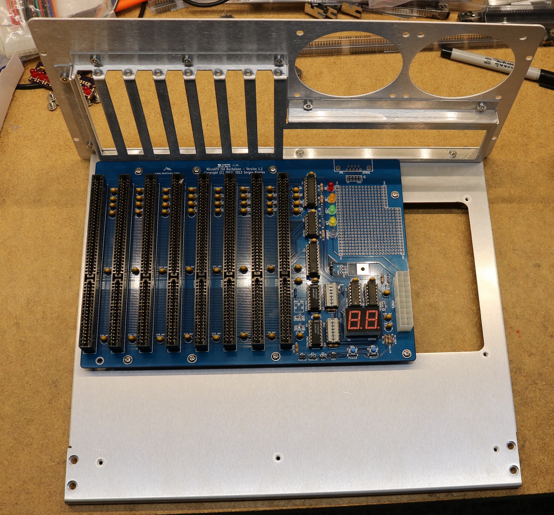
Here’s an early picture of the backplane. I started with just two card edge connectors installed, since I found edge connectors cheap on eBay and wanted to make sure they were decent before committing to soldering all of them:

Backplane with two edge card connectors installed

Here’s a picture of the backplane with the remaining components installed, right before I power-up tested it. Note that I had some 2×8 shunts that I installed next to the 7-segment drivers. You only need 7 spots, so I cut them down into 2×7 shunts. These shunts tend to come in handy.

Xi 8088 backplane with components installed

Note that the backplane is 16-bit whereas the Xi 8088 CPU card itself is only 8-bit. The Xi 8088 CPU card does have the ability to pass some additional signals on the 16-bit connector. In particular it includes some additional IRQs, as well as MEMW, MEMR, and LA17-LA19.Using a 16-bit backplane also affords the opportunity to use a 16-bit CPU in the future should a 16-bit CPU board ever become available.

Building the CPU board

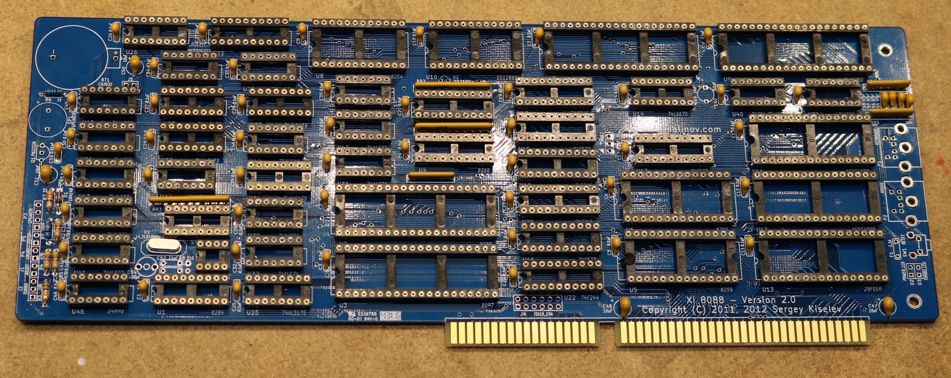
Next up was the CPU board. I started with the capacitors and SIP resistors, thinking they were shorter than the IC sockets and it would be easier to do them first. I was wrong. They were slightly taller than the sockets, and this caused me a bunch of unnecessary grief installing the sockets. Won’t make that mistake again!

Xi 8088 CPU board with caps and resistors installed

Xi 8088 CPU Board with sockets installed

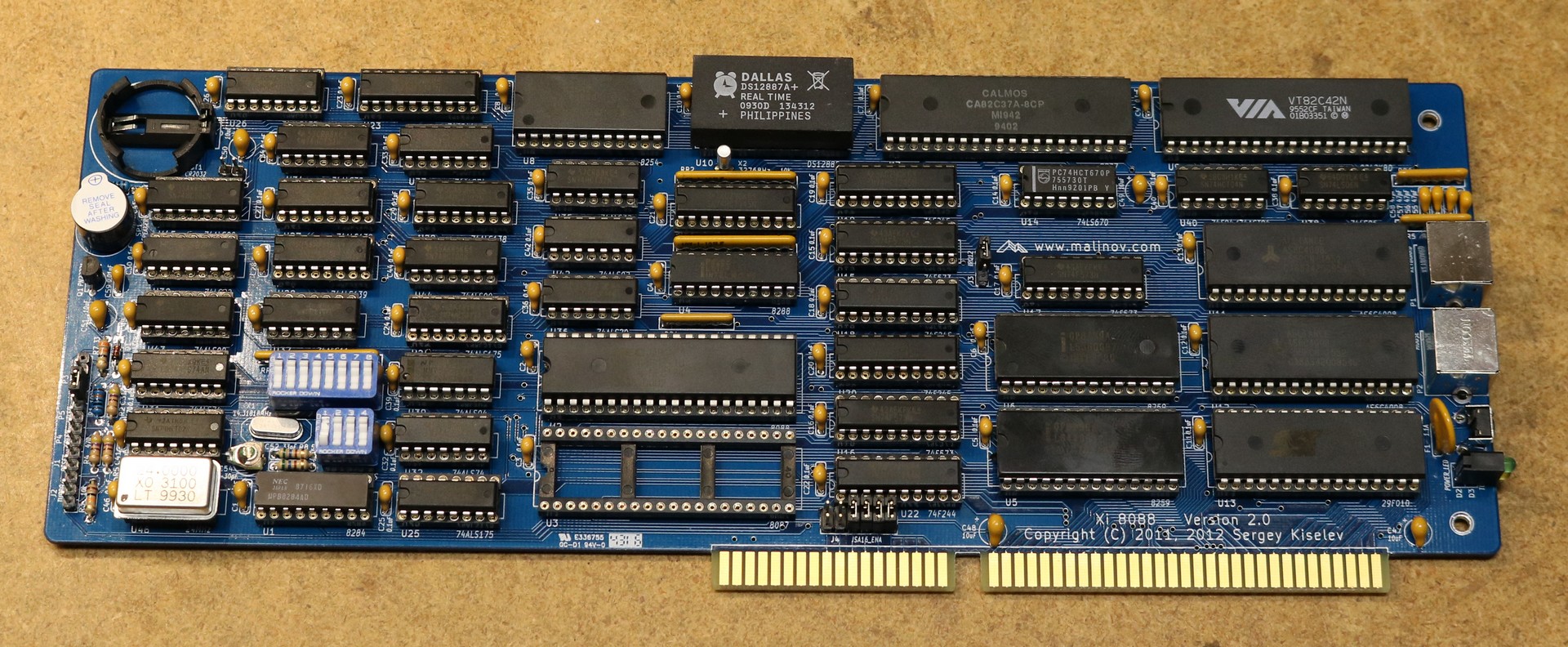
Xi 8088 CPU Board Completed

You notice one socket is left unpopulated. That’s for an 8087 coprocessor. Back in my PC days, I never had the floating point coprocessor, so I never bothered. In this build, unless you plan on doing floating point computation, it’s just a waste of money and watts. For the CPU I chose a Nec V20. I’m not sure if I ever owned a V20 (I kinda think I did), but it offers a bit better performance than the stock 8088. I installed a 24 Mhz crystal to support a Turbo of up to 8 Mhz.

I used a DS12887A+ RTC, which doesn’t require an external battery or external crystal. I soldered in the 32.768 Mhz crystal and battery socket before I realized this. They don’t hurt anything.

I procured a TVGA 8900B card from eBay to use until I built my own VGA card. When looking for VGA cards, most are 16-bit. Make sure to get one that can be jumpered for 8-bit operation.

My first power-on test with the CPU didn’t go so well. The board made an obnoxious squealing sound. This is because I decided to save a $1.50 by using a speaker from the “junk box” rather than buying the recommended one. My “speaker” turned out to be a buzzer. Don’t do that. The other issue was that the POST display didn’t work right. This turned out to be because one DM9368 was DOA and the other had a bad segment. Buy your DM9368s from a reputable supplier.

After fixing these few issues, I managed to get it powered up and saw output on the VGA. The Bios worked. The keyboard worked. I couldn’t boot yet, because I didn’t have a storage device.

Choosing a case

I felt really concerned about operating it sitting on the workbench, as one careless stumble could easy break something. While I did run a motherboard with no case back in the 80s, you feel a lot differently when you just spent hours soldering things together. So I decided to go about building or buying a case. Engineering the rear panel with cutouts for expansion slots seemed like a lot of work, so I settled on this “motherboard tray” by mountain mods:

Backplane in Mountain Mods motherboard tray

I did have to modify the case slightly to accommodate the backplane. The issue is demonstrated in my video — the backplane lined up with the right edge of the case rather than the left, only allowing four slots to line up with the slot cutouts. I ended up drilling some additional holes and installing some additional studs. An easy-to-solve problem.

Building the floppy controller

We can’t get very far without a storage device, so next up is the floppy controller:

Xi 8088 Floppy Controller

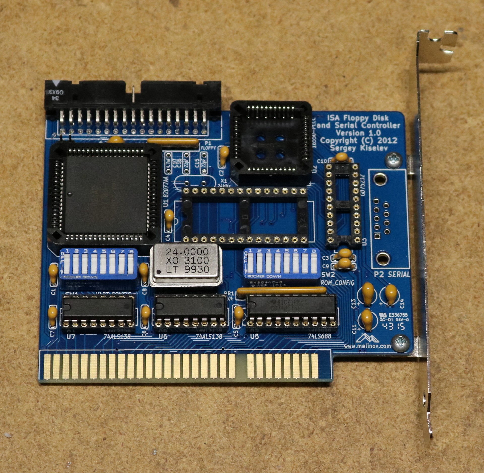
The floppy controller that Sergey designed includes both a floppy controller and a serial port. I only needed the floppy controller, so I eliminated some of the parts necessary for the serial port. The board does have a couple of big imposing-looking PLCC sockets, but they are through-hole sockets and not that difficult to solder. If you can solder a through-hole DIP socket, then you can solder a through-hole PLCC socket.

A minor complication was that I didn’t have the needed 24 Mhz crystal. I did, however, have some 24 Mhz oscillators (whenever I buy something, I always buy two or three, to have spares). I put the 24 Mfz oscillator in the serial port’s oscillator socket, and installed a jumper wire (hidden behind the board) plumbing that oscillator through to the floppy controller. It work fine and was a good hack until I got around to ordering some 24 Mhz crystals.

After that, I booted DOS 3.31 from a floppy. It worked out fine.

Building the OPL2 sound card

To be written…
Building the Compact Flash storage card

To be written…
Building the VGA Card

To be written…

Closing Thoughts

To be written…

Z80 Retrocomputing 17: Enhanced Z80 CPU Board for RC2014

$
0
0

I set out to build a fancier CPU board:

Design

I wanted the CPU board to have the following features:

  • on-board oscillator, so that a separate clock board is not necessary
  • power-on reset circuit
  • reset header for external reset switch
  • status LEDs for common signals such as RD, WR, MREQ, IOREQ, M1, and HALT

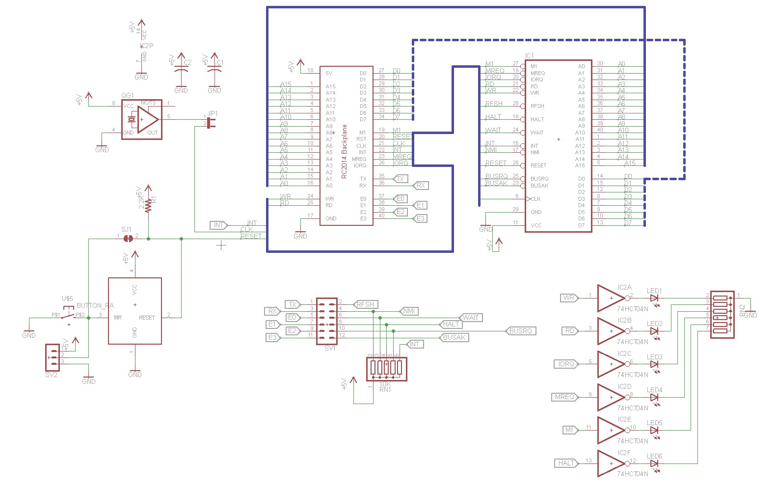
Below is the design that I came up with:

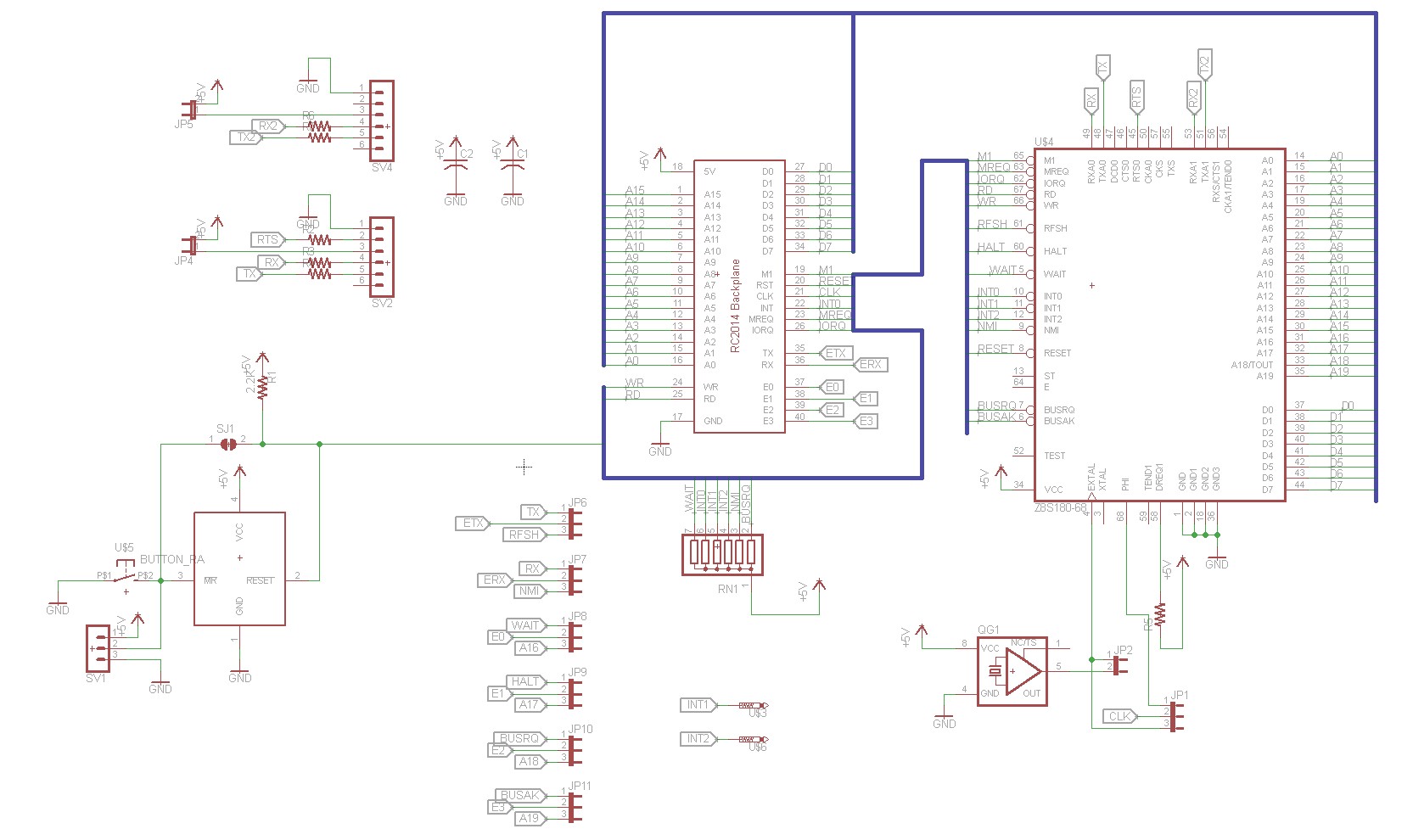
RC2014 Enhanced Z80 CPU Board Schematic

The oscillator footprint is entirely optional and can be selected by jumper JP1. Regardless of the setting of this jumper, the Z80 is connected to the RC2014 BUS’s CLK pin. So that mean that if you leave JP1 unjumpered, you can use an external clock board. If you install the osciallator and jumper JP1 then you had better not have installed an external clock board, as you would end up with two clocks operating simultaneously.

Status LEDs are operated by a 74HCT04 hex inverter. The inputs of the hex inverter are connected to WR, RD, IORQ, MREQ, M1, and HALT respectively. A SIP resistor handles current limiting for the LEDs.

I used a MAX811 for the power-on reset circuit. See my blog post on Z80 Reset Circuits for more information.

That’s about it, this is a pretty simple board.

Implementation:

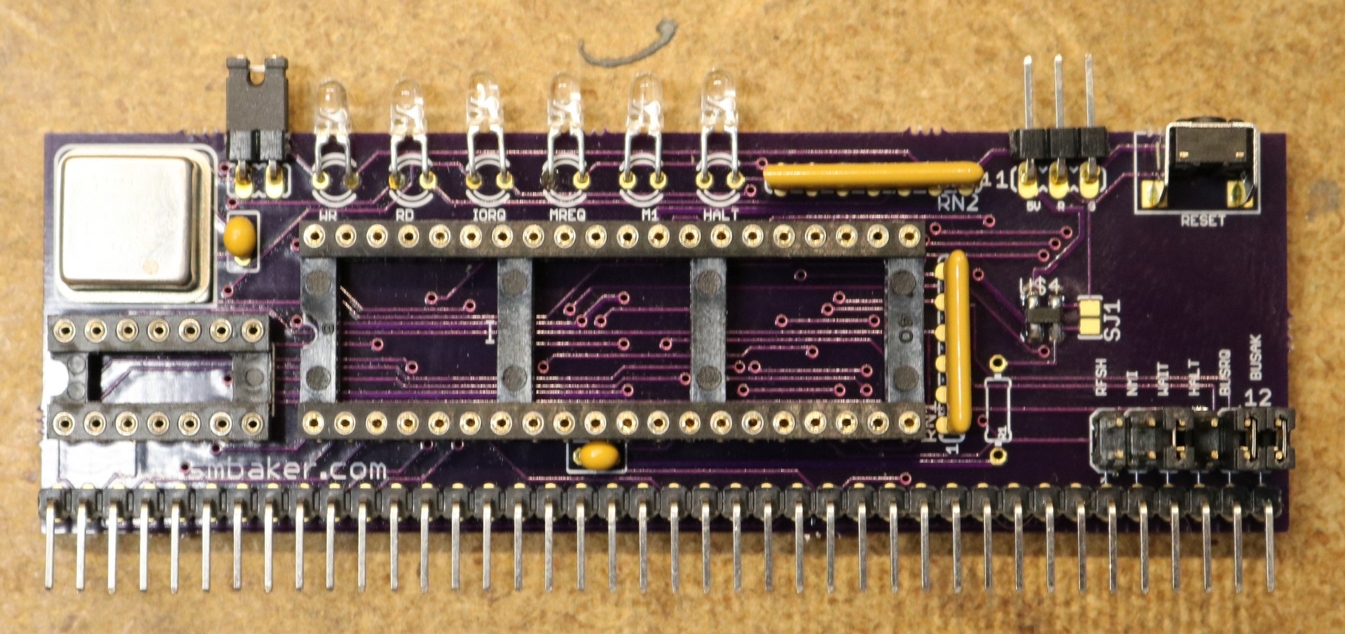
I build two of these:

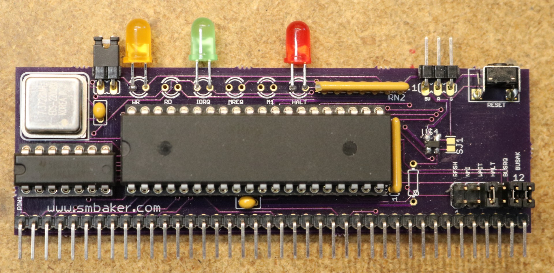
RC2014 Enhanced CPU Board with all six LEDs

RC2014 Enhanced CPU Board with just three LEDs

The first one had all six LEDs, but that turned out to be overwhelming. As long as the CPU is running at typical megahertz speeds, the M1, MREQ, and RD lights appear to be lit all the time. This is because unless it is halted, the CPU is pretty much always fetching instructions. I used high-efficiency blue LEDs, so it was also really bright and hard on the eyes to look at.

For my second prototype, I installed only the LEDs that show useful information — Halt, IORQ, and WR. The Halt LED will light up when the CPU is halted. For RomWBW that’s not too interesting, but for Fuzix it’s cool as the CPU Halts everytime Fuzix is idle. The WR LED lights up for both memory and IO writes. The IORQ light lights up for IO reads and writes. This is useful, when you access the disk or terminal or do something else IO-heavy, you’ll see lots of activity on IORQ. Programs that are writing to a lot of memory will have the WR light lit a lot.

If I was to do this over again, I’d probably use a NAND gate, so that I could break out IO-Write, IO-Read, and Memory-Write.

PC-Boards

As usual, I’ve made the board available on OSH Park for anyone who is interested:

Order from OSH Park

Z80 Retrocomputing 18 – Z180 CPU Board for RC2014

$
0
0

In this video, I design and build a Z180 CPU Board for the RC2014

Motivation

I wanted to try a CPU that runs at faster clock speeds and has more built-in peripherals than the Z80. More built in peripherals means less external boards needed for mundane features, and more room in the backplane for “interesting boards”.

Selecting a CPU

There are several variants of the Z180. I chose the Z8S180 because it is available in a PLCC package, which means you can mount it using a through-hole PLCC socket. The latest and greatest version offers a few more features than the Z8S180, but is only available in QFP. On-board peripherals of the Z8S180 include:

  • Interrupt controller, featuring three maskable interrupts and one non-maskable interrupt
  • Two DMA controllers
  • Two Asynchronous Serial Interfaces, one featuring a full set of handshaking signals (CTS, RTS, DCD)
  • Memory-management unit that allows up to 1 MB of pageable memory
  • Clocked Serial IO port
  • 16-bit Programmable Reload timer, usable as a baud rate generator
  • Timing generator that interfaces with a crystal or an oscillator, and can operate the cpu at 2X, 1X, or 0.5X the speed of the crystal.

The Asynchronous Serial Interfaces and Programmable Reload Timer should in theory mean no need for the Z80 CTC or SIO/2 that I tend to use in my other projects. The MMU has the potential to eliminate much circuitry on the banked ROM/RAM board.

Design

Below is the schematic for the Z180 board:

RC2014 Z180 CPU Board Schematic

As you can see, the bulk of the schematic is the Z180 CPU and RC2014 backplane connector. We do the obvious thing, and connect all of the address, data, and control lines from CPU to backplane.

It gets a little more interesting where the oscillator is connected. The Z180 has both a clock input (EXTAL) and a clock output (PHI). This allows peripherals to take advantage of the Z180’s software-controllable clock multiplier and divider. I wanted to make sure the board was compatible with external clock boards (like a slow clock, etc) so I made it so the RC2014’s CLK pin could be jumper to either the clock input (EXTAL) or the clock output (PHI). I also put the usual on-board footprint for a crystal oscillator, with a jumper to enable it to be connected to EXTAL. This should pretty much support any type of clocking that one wants to do with an RC2014.

Note that if you intend to use the RC2014 serial boards, either a ACIA or SIO/2, then you’ll have to either run your Z180 at 7.3728 Mhz, or clock the ACIA or SIO/2 boards separately, since they generally derive their baud rate clock from the RC2014 bus. I built a oscillator footprint into my SIO/2 board for exactly that reason.

There’s also a MAX811 power-on reset circuit, and a smd jumper to work around it if you don’t want it. There’s a header for external reset switch and a footprint for onboard reset button.

Because the Z180’s onboard MMU has support for addressing up to 1MB of memory, there are several extra address lines to contend with. I designed this board so that you can select the RC2014’s extra pins between the traditional functions of my other CPU boards (busreq, busack, halt, wait, etc) and the address pins. I’m thinking this will allow me to develop a banked ROM/RAM board that uses the Z180’s MMU instead of its own page selection circuitry.

The serial headers are broken out to FTDI-compatible jumpers.

Implementation

Below is a picture of the assembled CPU board.

RC2014 Z180 CPU Board Assembled

As we can see, I’ve installed a 20 Mhz oscillator (I socketed this oscillator so that it can easily be changed). The jumpers are installed to connect the oscillator to EXTAL and to connect the Z180’s PHI to the RC2014 BUS’s CLK pin. By default, the CPU will boot up with the divide-by-2 clock divider selected, so it runs at 10 Mhz. This divider is then disabled in software and the CPU switches to 20 Mhz. I’ve modified RomWBW to do this.

Important Notes

I have tried out any of the onboard peripherals yet. I’m still using my SIO/2 board for asynchronous IO until I get around into looking into Z180 serial drivers. As mentioned above, this necessitated installing a 7.3728 Mhz crystal in my SIO/2 board, so that the SIO/2 board has the correct reference for baud rate generation.

PCB Availability

As usual, I’ve made the board available on Osh Park:

Order from OSH Park

ISA Speech Synthesizer board using SP0256A-AL2

$
0
0

I’ve done a few speech synthesizer posts already using the SP0256A-AL2 chip by general instruments. We’re at a relatively fortunate time in that there are some authentic functional chips available on eBay. As always, make sure you do your research and make sure you’re buying from a reputable seller, or at least someone with a decent return policy. Anyhow, I ended up with a good supply of chips, so I thought I’d try to make an ISA speech synthesizer board for my Xi 8088 PC/XT compatible.

Brief intro to the SP0256A-AL2

The SP0256A-AL2 is a phonetic speech synthesizer. It breaks speech down into 64 different phonemes (including some pauses) that allow you to effectively create arbitrary english speech. It does not in and of itself offer text-to-speech capability. You are responsible for the logic that converts text into phonemes. For example, to say my name (Scott), one has to send the phonemes “SS KK2 AO PA3 TT1″. The IC has a parallel interface with 8 data bits and a “LRQ” (Load Request) pin that tells the IC to load the phonemes that are on the data bus. There are two status pins, ALD and SBY. ALD will go active when the IC is ready for a new phoneme to be loaded. SBY will go active when the IC is busy.

Design

Here is the schematic that I came up with:

ISA Speech Synthesizer Schematic

The upper left corner is the 62-pin ISA bus. Typically on my ISA cards I use both the typical ISA edge card connector as well as a dual-row header. The header makes it easy to attach debugging leads if necessary, or to hack things up in the case of a mistake.

Upper middle has the address decoding section. I used a 74HCT680 identity comparator. What the 680 does is to compare two sets of data lines (P and Q). If all of the P bits are equal to all of the Q bits, then it will assert its output. This makes it perfect for using a dip switch to select addressing. The ISA bus allows 10 bits of addressing, but the 680 only supports 8 bits, so I chose to use the upper 8 bits. Thus the speech synthesizer will occupy four consecutive port addresses. I tend to put it at address 0×120, so it ends up occupying 0×120 – 0×123. Once the address is selected, we need to do a little more work to get our read and write strobes. This is done with a 74HCT32 OR gate. We OR the address select together with the ISA BUS’s RD signal to get a CSR (chip-select-read) and we OR the address select with WR to get a CSW (chip-select-write). The CSW signal we can feed directly into the SP0256A-AL2’s LRQ pin.

Upper right has some hex inverters. The primary need for this is the RESET signal. The ISA BUS reset line is active high, whereas the SP0256’s is active low. So we just need to invert it. I also brought out a header in case we’d like to try connecting to speech synthesizer to an interrupt, so we could try an interrupt-driven approach instead of polling. Finally, another inverter is used to drive a LED that will light whenever the speech synthesizer is talking. Maybe the LED would be handy if you’re experiencing an audio-output issue, but really it’s just there for added sparkle.

The bottom half of the schematic is dominated by the SP0256A-AL2. To the left of the SP0256A-AL2, we have a 74HCT245 that I use to allow us to poll the SBY and LRQ signals. It’s selected by the CSR signal that came out of the address decoding. Basically, if we write the speech synthesizer port, we’ll cause a phoneme to be spoken. If we read the port, then we’ll poll the two status lines. To the right of the SP0256A-AL2 is the audio amplifier — it’s straight out of the Radio Shack datasheet.

Implementation

As usual, I used Osh Park to fabricate the PC Board. Here is the board after all components have been soldered:

ISA Speech Synthesizer, completed board

The only thing that’s really noteworthy about the PC-Board is that I didn’t make it quite tall enough to mount the keystone bracket, and I had to use a small 4-40 right angle bracket from Sparkfun to securely attach the keystone bracket to the card. The pot is also a little on the tall side and just barely misses the slot cutout in a typical PC case. Next time I’ll probably try to make the PC-Board card a little taller so the bracket is more straightforward to attach (generally, I make PCBs as small as possible, to save on money).

The dip switches as shown are set to address 0×120 (keep in mind, these are the upper 8 bits of the 10-bit port address).

Software

I wrote a driver for the speech synthesizer board, in Turbo Pascal. The driver is available at https://github.com/sbelectronics/pctalker. It has a few different ways that you can use it. If you use the -D option, then it will speak the phonemes directly. For example,

say -D SS KK2 AO TT1

If you use the -L and -B options, then it will install itself as a TSR and attach itself to lpt3. This allows you to use DOS commands like ECHO or TYPE to send output to the speech synthesizer at any time, and it will talk in the background. For example,

say -L -B

echo “SS KK2 AO TT1″ > lpt3

Board Availability

As usual, the PCB is up on Osh Park:

Order from OSH Park

Viewing all 118 articles
Browse latest View live