In this blog post, I design a single step module for the RC2014.
[TODO: Insert Video Here]
If you haven’t read my introduction to retrocomputing yet, then please start there, as it describes the Z80 platform that I’m using.
The single step module is an alternative to the bus supervisor that I designed in the previous blog post. The bus supervisor implemented a slow clock, but it required a raspberry pi to do so. I wanted to design a module that required no raspberry pi, and added the ability to single-step and to auto-step the CPU. So why single step? Single-stepping is another feature that is handy for assembly language debugging. It allows you to execute exactly one instruction at a time. For each instruction, the CPU will wait for the user to press a button.
Auto-stepping is the other feature that this board implements. Rather than require the user to push the button, we can use a 555 timer to “push the button” for us. This makes the program run slowly, for example at a rate of 10 instructions per second or 100 instructions per second.
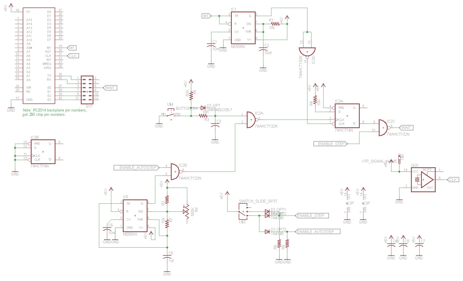
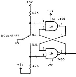
As the basis for my single stepper, I used this post at the Z80 Computer Project blog. It starts off with a circuit designed by Steve Ciarcia and published in his book Build Your Own Z80 Computer, which is available online. Ciarcia’s design uses a flip-flop to implement the single stepping. The M1 signal is fed into a one-shot and used as the clear signal for a 7474 flip-flop. The M1 signal clears the flip-flop, which sets the Z80 wait line low. This will cause the Z80 to wait until the wait line is set high again. A debounced pushbutton is used to clock a “1″ into the flip-flop, which will in turn raise the wait line and unblock the CPU. The next M1 cycle will clear the flip-flop and re-enter the wait state.
The Z80 Computer Project blog post replaced the monostable multivibrator used in Ciarcia’s circuit with a 555 timer. My modification replaces the SPDT step switch with a SPST pushbutton:
One thing to note — both the Ciarcia book and Z80 Computer Project Blog showed the Pre input (pin 4) of the 7474 flip-flop unconnected. This caused chaos in my implementation. Sometimes it would work fine, other times the flip-flop would pick up noise and the wait pin would oscillate. I terminated pin 4 to 5V and the chaos went away.
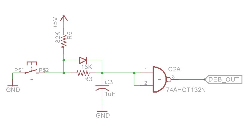
The idea for the switch debounce came from The Ganssle Group’s blog post on switch debouncing. So what is switch debouncing? When you flip a switch or push a button, it doesn’t simply change from one state to the other, there’s a noisy phase where the state flips back and forth a few times as the metal is just starting to touch. This will glitch your typical DC logic circuit. So we need some circuit to filter out the noise and get us only the state change event from the switch.
Ciarcia’s circuit used an SPDT switch and a couple NAND gates SPDT buttons aren’t super easy to find, and I wanted to use a SPST button. So I tried the RC schmitt trigger switch debounce circuit shown in the above schematic. The RC uses a network turns the noisy switch closure into a slower capacitor discharge, and the switch opening into a capacitor charge. Since it takes time to charge or discharge the capacitor, we eliminate the noisy spikes.
Note that the diode in the above schematic is optional, and is not necessary given the resistance values used above. The ganssle blog post gives the appropriate math.
The first time I built the circuit, I made the mistake of connecting the RC network to a plain ordinary 74HCT00 NAND gate. It’s important that you use a Schmitt trigger NAND gate,74AHCT132N. The Schmitt trigger includes hysteresis, which is necessary to prevent false triggering on the switch debounce. You can read more about Schmitt triggers on wikipedia.
The other change I made to the circuit is adding the autostepping feature. This is a second 555 timer configured as an oscillator. A NAND gate is used to enable or disable the output of the 555, and another NAND gate is used to combine the 555’s output with the pushbutton. Basically what happens is the 555 timer pushes the button for us. The values given in the schematic allow you to adjust the frequency from just under 1 Hz to around 100 Hz. It’ll depend on the specific capacitor you have as capacitors often have a fair amount of tolerance.
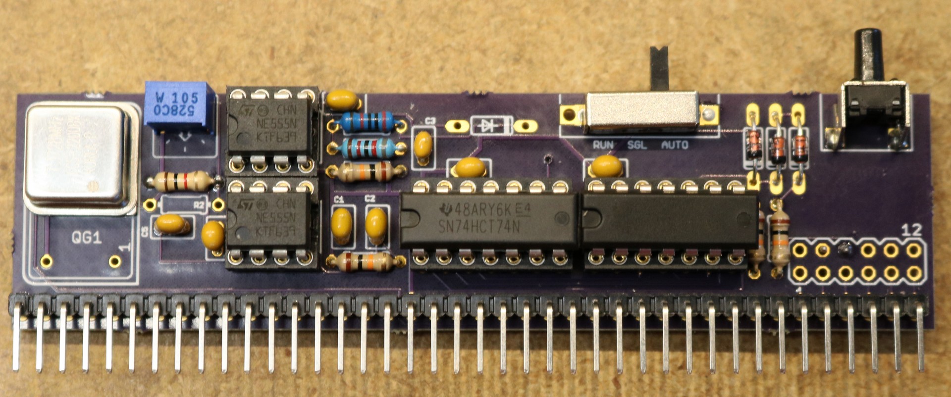
There’s a selector switch that lets you select “Run”, “Single”, or “Auto” modes.
Also on board is an optional 7.3728 Mhz oscillator. This allows the single step board to replace the RC2014’s clock board, saving a slot in the backplane.
Here is a picture of the completed single stepper module:


