I wanted more lights on the retrocomputer, so I decided to add a bus monitoring board.
For a brief introduction to my retrocomputing posts, please start at the first one.
So what exactly does the bus monitor board do? It monitors the Z80 address and data buses and displays the current values on those buses on hexadecimal displays. This allows you to, for example, see what IO ports are being read and written, or what memory addresses are being written.
When designing this board, I faced a few options as to how to display the output. A lot of retrocomputer designs will use simple LEDs and display the output in binary. That’s neat (blinking lights are always neat) but not too useful unless you’re quick at doing binary to hex conversion in your head. I looked around on ebay, and eventually came up with some hexadecimal displays, the TIL311. The TIL311 can display a single hex digit (0,1,2,3,4,5,6,7,8,9,A,B,C,D,E,F) from a four-pin binary input. It has an onboard TTL driver to do this.
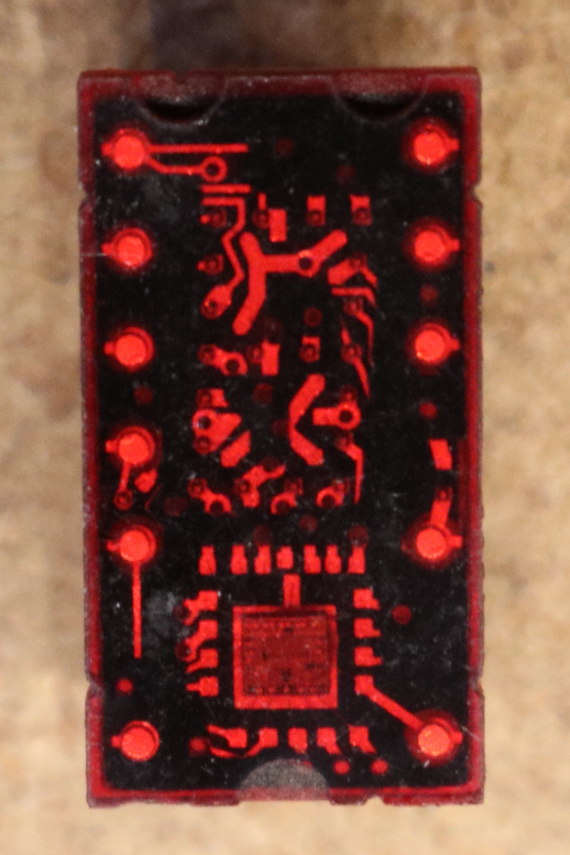
Above is a picture of one of the TIL311 I purchased on ebay. It’s really very small, the whole thing fits a 16-pin DIP socket. The LEDs are in the top half of the TIL311, and the TTL driver logic is in the bottom half.
Examining the TIL311 datasheet, I came across the first hurdle to be overcome. The TIL311 is a TTL device. It will sink 1.6 ma if a logic low is placed on one of the input devices. The Z80 only provides 1.8 ma of drive current, and the RC2014 is designed with an unbuffered data bus. A single TIL311 display would pretty take the entire Z80 output drive current, severely loading the bus. For this reason, I had to add buffers in front of the TIL311. I chose the 74HCT244N.
The next question was what data I wanted to display on the TIL311. At first this seems obvious, I want to display 16-bits (four hex digits) or address bus and 8-bits (two hex digits) of data bus. However, just attaching the TIL311 to the bus and displaying everything isn’t necessarily a good idea. The RC2014’s Z80 is running at 7.3728Mhz, and simply displaying the bus during normal operation is going to lead to a rapidly changing unreadable display. It’ll change so fast that you probably won’t even be able to see it.
The solution I chose was to add some configurable latching capability. I broke out the M1, MREQ, IOREQ, RD, and WR signals to a dip switch so that those signals can be used to trigger the latch on the TIL311. If you select M1, then in theory you should be able to see every instruction load address. If you select IOREQ then you should be able to see every IO request. Watching instruction loads at 7.3728Mhz is still not something the human eye can perceive, but io requests happen much less frequently and you can actually see stuff happen.
Furthermore, I’m planning on adding a single-stepper and a slow clock board at some point, and once that’s done, then watching memory requests and instruction fetches may be useful.
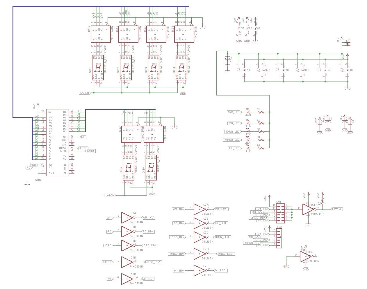
Here’s the resulting schematic of the bus monitor board:
The TIL311 displays and the 74HCT244N buffers should be pretty straightforward. We can probably use some description of what all of the hex inverters are doing… In addition to buffering the address and data pins, we also need to buffer any control signals we want to display. One option would have been to use a buffer chip, but a hex inverter works just as well (we just need to invert the signal twice). So we invert each control signal once, feed them all to the DIP selector switch, and then invert the selected one again, which we then use to drive the latch pin of the TIL311.
In addtional, I’ve used some 74HC05 open collector inverters to drive the LEDs. The open-collector inverter doesn’t provide any significant current for high output, but it is capable of sinking a low output, perfect for sinking a LED. This allows us to add five LEDs for displaying the status of M1, MREQ, IOREQ, WR, and RD.
Note that if a 74HCT04 is used for IC1 as shown in the schematic then you have to be careful not to engage two dip switches at the same time (lest one inverter output a high while another is outputting a low and the DIP switch shorts them). One option is to use a 74HCT05 for IC1 instead, and add pullups. This allows you to enable multiple DIP switches at the time, and it will “AND” the signals together. For example, flipping the WR and IOREQ DIP switches at the same time will latch the displays only when WR and IOREQ are both low, effectively displaying only io writes and not io reads.
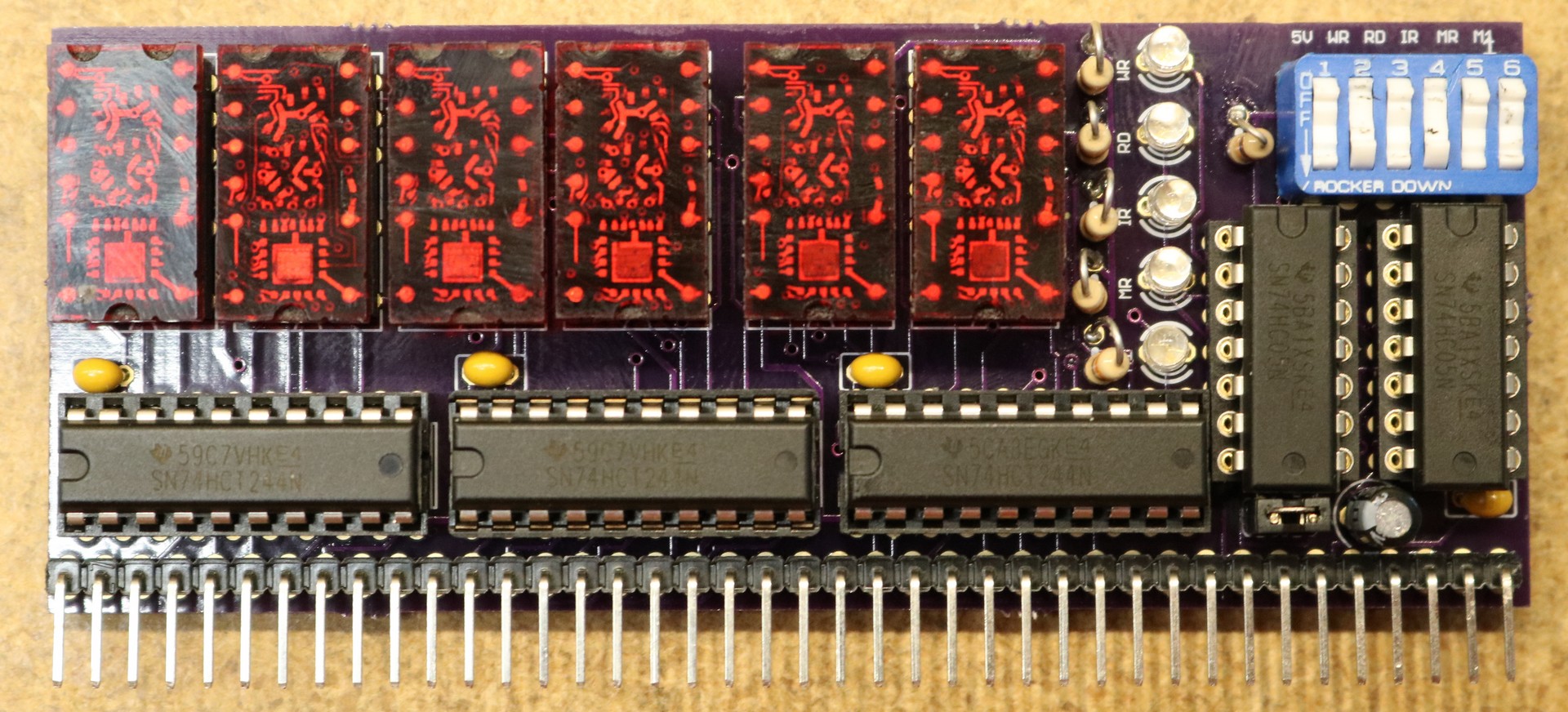
Here’s the assembled bus monitor board:
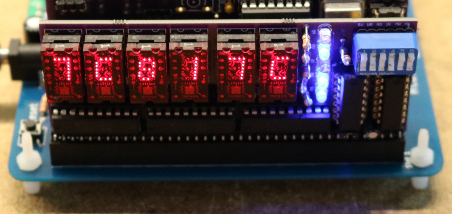
Finally, here’s a picture of the board in the front slot of the RC2014, displaying IO requests:
One word of caution — these displays take a lot of current to run them. When I first plugged this board into my RC2014, I exceeded the capability of the un-heatsinked 7805 regulator and put it into thermal shutdown. I have since replaced the 7805 with a switching regulator from EZSBC.


